Continue to Site

Welcome to EDAboard.com

Welcome to our site! EDAboard.com is an international Electronics Discussion Forum focused on EDA software, circuits, schematics, books, theory, papers, asic, pld, 8051, DSP, Network, RF, Analog Design, PCB, Service Manuals... and a whole lot more! To participate you need to register. Registration is free. Click here to register now.

[SOLVED] power supply online design tool for 3 phase based smps

Status
Not open for further replies.

mamech

Full Member level 3
Joined
Nov 9, 2010
Messages
176
Helped
0
Reputation
0
Reaction score
0
Trophy points
1,296
Activity points
3,135
hello

some months ago I used several online smps power supply design tools, like the toold on st, ti, fairchild, etc...

most of them was useful and easy , but sadly all of them were based on single phase application.

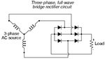
currently I need design a power supply with 3 phase AC input, and 2 DC outputs, one is 3.3V , 500mA, and the other is 5V , 2 A .

Does anyone here knows a good and reliable any design tool so I can get the components and schematics from it?

also, if any one knows a ready made desing, it will be welcome too . I found some application notes on ST about same topic, but sadly the output channels were 3.3, 100mA, and 5V, 500mA, which means that their design is in need for editing, and I do not have enough knowledge to customize their design for my specs.
 

Hi,

For me a three phase SMPS for a total of less than 12W output power seems to be overkill.

Why 3 phase?

Klaus
 

As the power is very low (13W) then then use two of the three phases. There is absolutely no reason to use all three phases. The input/output MUST be transformer isolated as what was the neutral is now 230V and any RFI capacitors must have adequate working voltage.
Frank
 

Hi,

For me a three phase SMPS for a total of less than 12W output power seems to be overkill.

Why 3 phase?

Klaus

because this is power/energy meter application, so the available source is 3 phase.

- - - Updated - - -

As the power is very low (13W) then then use two of the three phases. There is absolutely no reason to use all three phases. The input/output MUST be transformer isolated as what was the neutral is now 230V and any RFI capacitors must have adequate working voltage.
Frank

actually, I thought to do this, but i found that application notes for power meters in TI and Microchip show something different. both of them takes 3 phase supply and use it to produce the needed DC supply voltage for logic circuitry. The mention that they do this, o if one of phases fail, then other phases can still do the job and supply the microcontroller.

the other strange thing, is that I asked in TI forum, and they told me that it i ok to have neutral to be common with microcontroller ground, and even with GSM/GPRS ground (I use GPRS/GSM module in my application), I felt that this is a little bit strange.
 

Hi,

While you need the voltage signal of all three phases, I see no need for a three phase power supply.Why?

10W for a power meter is huge. It's about 90 kWh per year.

Klaus
 

there can be a lot of electronics in these three phase power meters.
I would just use a three phase rectifier and then a flyback say to get the dc from there.
Power integrations may have solutions.
If not just get a current mode controller and go from there.
 

Hi,

While you need the voltage signal of all three phases, I see no need for a three phase power supply.Why?

10W for a power meter is huge. It's about 90 kWh per year.

Klaus

I will explain more about why the current rating is huge.

the original design based on microchip application note no 51723a, shows that the power supply has 2 ouptuts; 3.3 volts , 0.25A, and the other output is 5 volts, 0.15A .

but in microchip design, they do not have GSM/GPRS Module. I need this in my application, so I needed to replace their power upply with another power supply that satisfy the power needs in presence of GSM/GPRS module.

regarding GSM/GPRS module, as I have been told on edaboard but in another forum, it needs really big amperage in the beginning and it then drops to few milliamps after the module connects. actually, I made an experiment and I saw that this is true. when I connected the module with a power supply of 800 mA, the performance is not stable (i.e sometimes it can connect, sometimes no), and it shows stable performance in presence of 2 A power supply. so that is why I decided that I need a channel of 5 volts and 2 A rating.
 

Hi,

O.k. GSM clarifies the 10W,

But i'd go for three phase SMPS if the power is 1500W or more ... But not with 10W.
What is the benefit? Why do you want a three phase SMPS?

Klaus
 

Hi,

O.k. GSM clarifies the 10W,

But i'd go for three phase SMPS if the power is 1500W or more ... But not with 10W.
What is the benefit? Why do you want a three phase SMPS?

Klaus

for me, I would prefer to pick up one of phases with the neutral and to use it for to make single phase smps power supply with 3.3 and 5 volt channels, but what makes me unsure, is that both TI and microchip, say that the powering needs to be from the 3 phases, so if one of them drops, the meter keeps working.
I have a question about this, first: what is the danger if the meter stops working if one of phases fails? I think I do not need to measure anything if not all the 3 phases are connected, is not it?

- - - Updated - - -

to understand the configuration that was used with both Ti and microchip, please look here :

https://ww1.microchip.com/downloads/en/DeviceDoc/51723a.pdf

**broken link removed**


please look at power supply part in each document.
 

Hi,

so if one of them drops, the meter keeps working.
That's the point. This makes sense.

I have a question about this, first: what is the danger if the meter stops working if one of phases fails? I think I do not need to measure anything if not all the 3 phases are connected, is not it?
No one of us can tell you. You should find this in your project specifications.

Klaus
 

No one of us can tell you. You should find this in your project specifications.

Klaus

actually, I am just asking if it is common in 3 phase meters to be working even if one of phases fail. but it looks more robust to me if the meter can tell me the failure is in which phase.
 

So you have three alternatives (perhaps?). The easiest is to use the neutral and use a single diode from each live phase to fire up the DC/DC converter. Also this gives you a voltage monitoring point for each phase within your piece of kit. One other way is to use phase to phase voltage without a neutral. For this you need three single phase transformers (415V-> 12V) and common one terminal of each to give you a LV neutral and a diode from each transformer to give you your + DC volts. The other way is to establish a local "neutral". String three capacitors from phase to the artificial neutral point. They will drop a voltage so their value needs to be calculated.
Frank
 
  • Like
Reactions: mamech

    mamech

    Points: 2
    Helpful Answer Positive Rating
I think trees nailed it in post 6. 3 phase bridge rectifier no neutral needed, it will work on Y or delta power. Then use a flyback and see Power integrations for app notes.
 

Attachments

  • 3-phase-bridge-rectifier.png
    3-phase-bridge-rectifier.png
    5.7 KB · Views: 165
  • Like
Reactions: mamech

    mamech

    Points: 2
    Helpful Answer Positive Rating
I think trees nailed it in post 6. 3 phase bridge rectifier no neutral needed, it will work on Y or delta power. Then use a flyback and see Power integrations for app notes.
That would need a flyback supply that can run off up to 650v dc.
Even more than that if there is a voltage surge.

Its a bit clunky, but three small transformers and a low voltage rectifier would probably be more robust and reliable.
 

So you have three alternatives (perhaps?). The easiest is to use the neutral and use a single diode from each live phase to fire up the DC/DC converter. Also this gives you a voltage monitoring point for each phase within your piece of kit. One other way is to use phase to phase voltage without a neutral. For this you need three single phase transformers (415V-> 12V) and common one terminal of each to give you a LV neutral and a diode from each transformer to give you your + DC volts. The other way is to establish a local "neutral". String three capacitors from phase to the artificial neutral point. They will drop a voltage so their value needs to be calculated.
Frank

thank you, these suggestions made things clearer to me. so if I use 3 phase rectifier with 6 diodes like the one that flapjack mentioned, I will need to use output with DC/DC converter to get the voltages that I need, right?

if yes, then this mean that I could be able to use online design tool of ST or fairchild.

but in such case, the input voltage of DC/DC converter will be designed to be 514 volts Dc, right?
 

but in such case, the input voltage of DC/DC converter will be designed to be 514 volts Dc, right?
Depends on where you are.
Nominal voltage in Australia is 240v with 215v to 265v supply range.
Phase to phase 1.72 times that up to 456v
Peak rectified 1.414 times that up to a really scary 645v dc.

Even at exactly 230 volts is 396 phase to phase and 559v peak.
 
Depends on where you are.
Nominal voltage in Australia is 240v with 215v to 265v supply range.
Phase to phase 1.72 times that up to 456v
Peak rectified 1.414 times that up to a really scary 645v dc.

Even at exactly 230 volts is 396 phase to phase and 559v peak.

it seems that 645 volts Dc is really scary, even if the online design tool of fairchild showed me an error when I entered this value in design parameters of DC/DC converter!

- - - Updated - - -

it seems that really it is needed to step down each phase using a transformer. but this may lead to a bulkier meter in size.
 

You may receive some flack suggesting step down transformers, but I believe it will be worth it for long term reliability and robustness.

Lightning surges into the power distribution system are far from unknown and a transformer with some surge protection may stand a slightly better chance of survival than some fragile electronics.
 
  • Like
Reactions: mamech

    mamech

    Points: 2
    Helpful Answer Positive Rating
When we designed an ARM network at Iris Systems Inc in mid-90's we only needed a watt of power and this included charging a large cap for Tx high power ISM microwave radio on demand any minute of the day. So all we needed was a ceramic hybrid with large R's and zener diode bridge for DC. THis was converted to several voltages for MC6805, UHF Rx/Tx , IR 2-way comm diag port and IR power disc rotation detector.

In your case, your power demand seems to be far greater.
So just choose the 3 phase transformer suggested and combine with a 3phase bridge rectifier.

T1 3P AC-DC converter, 220V - 12V/5V Sanki DB-12CY220

the T1 3P AC-DC converter, 220V - 12V/5V Sanki DB-12CY220 is the same that is mentioned in microchip application note, but I searched many times in farnel and digikey or even on google, and I could not find where to order this, or what is the site of sanki company.

from where can I order it?
 

Status
Not open for further replies.

Similar threads

Part and Inventory Search

Welcome to EDABoard.com

Sponsor

Back
Top