Vermes
Advanced Member level 4

- Joined
- Aug 2, 2011
- Messages
- 1,163
- Helped
- 0
- Reputation
- 0
- Reaction score
- 0
- Trophy points
- 1,316
- Activity points
- 22,318
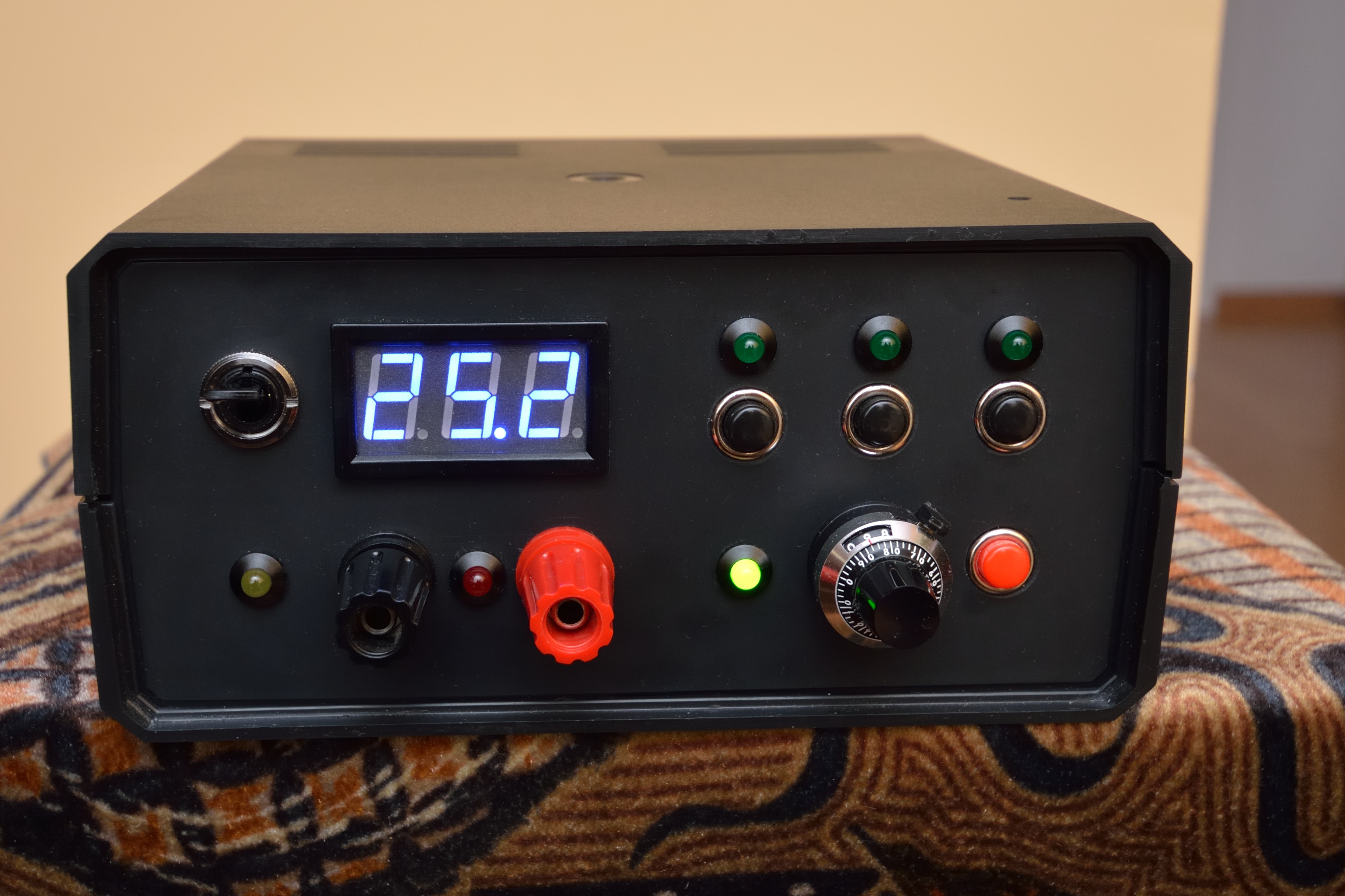
This power supply is an useful item in every electronic workshop. It can be used to test circuits. The power supply provides 15V/1.5A what can be great opportunity when using computer for tests is not enough for you.
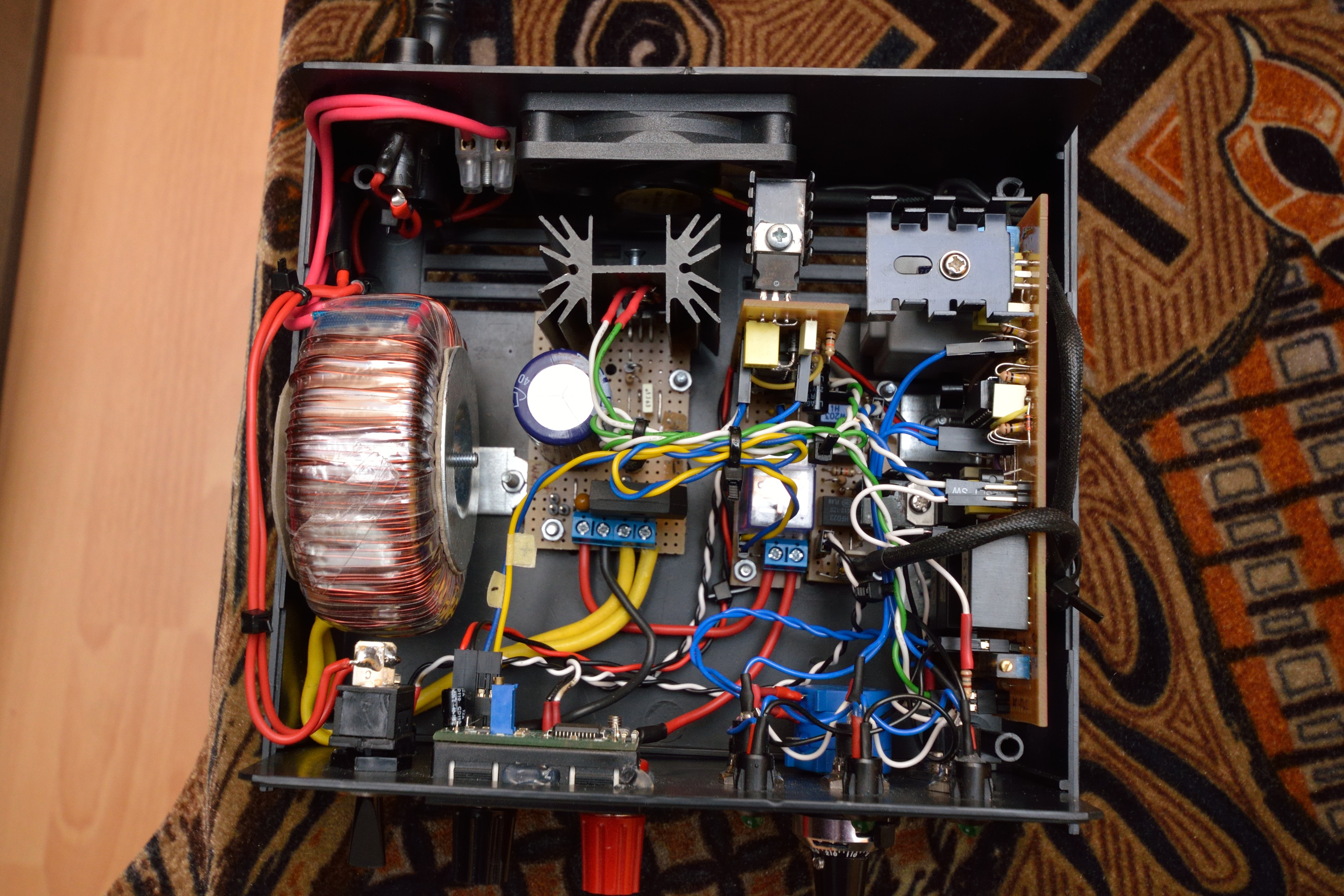
Construction consists of five modules:
- the power supply
- voltage switching system
- short circuit indication system
- thermostat
- voltmeter module
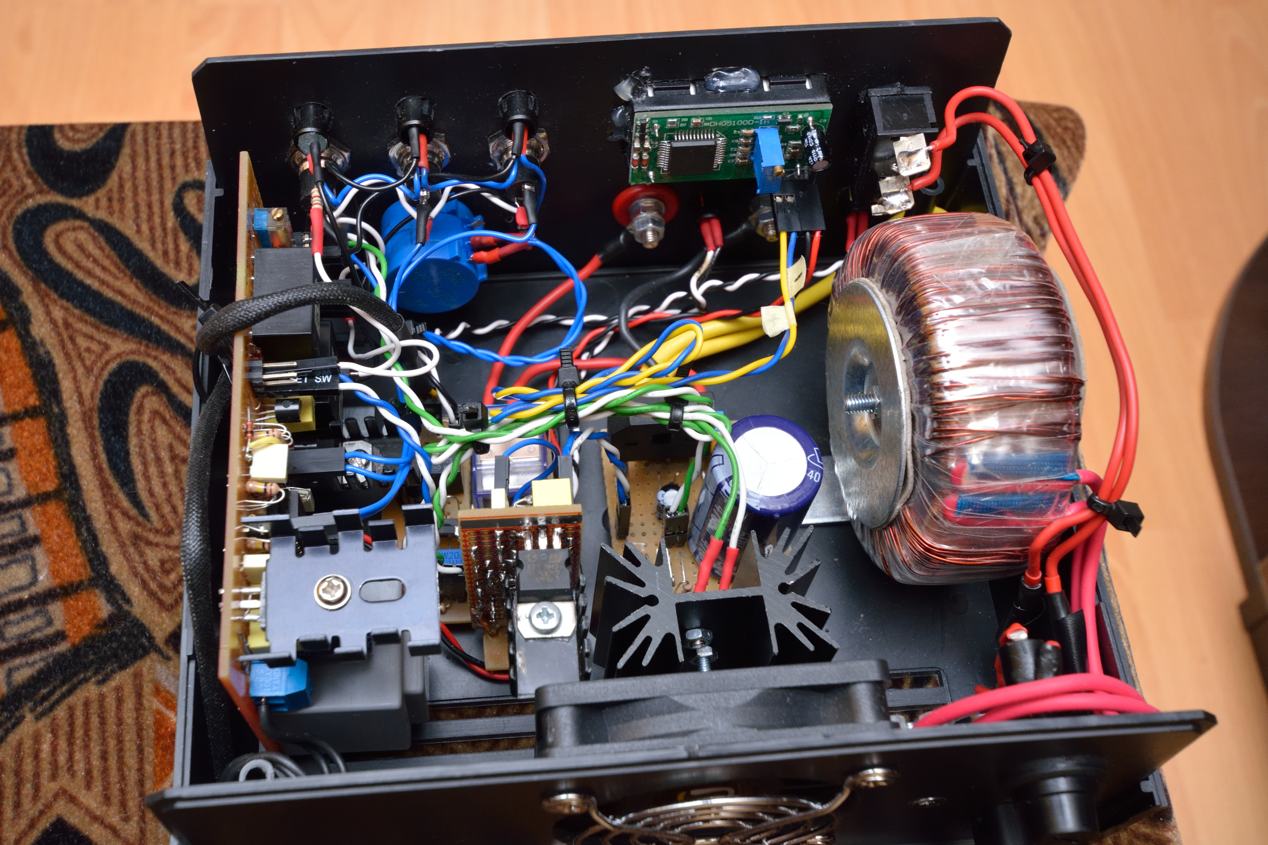
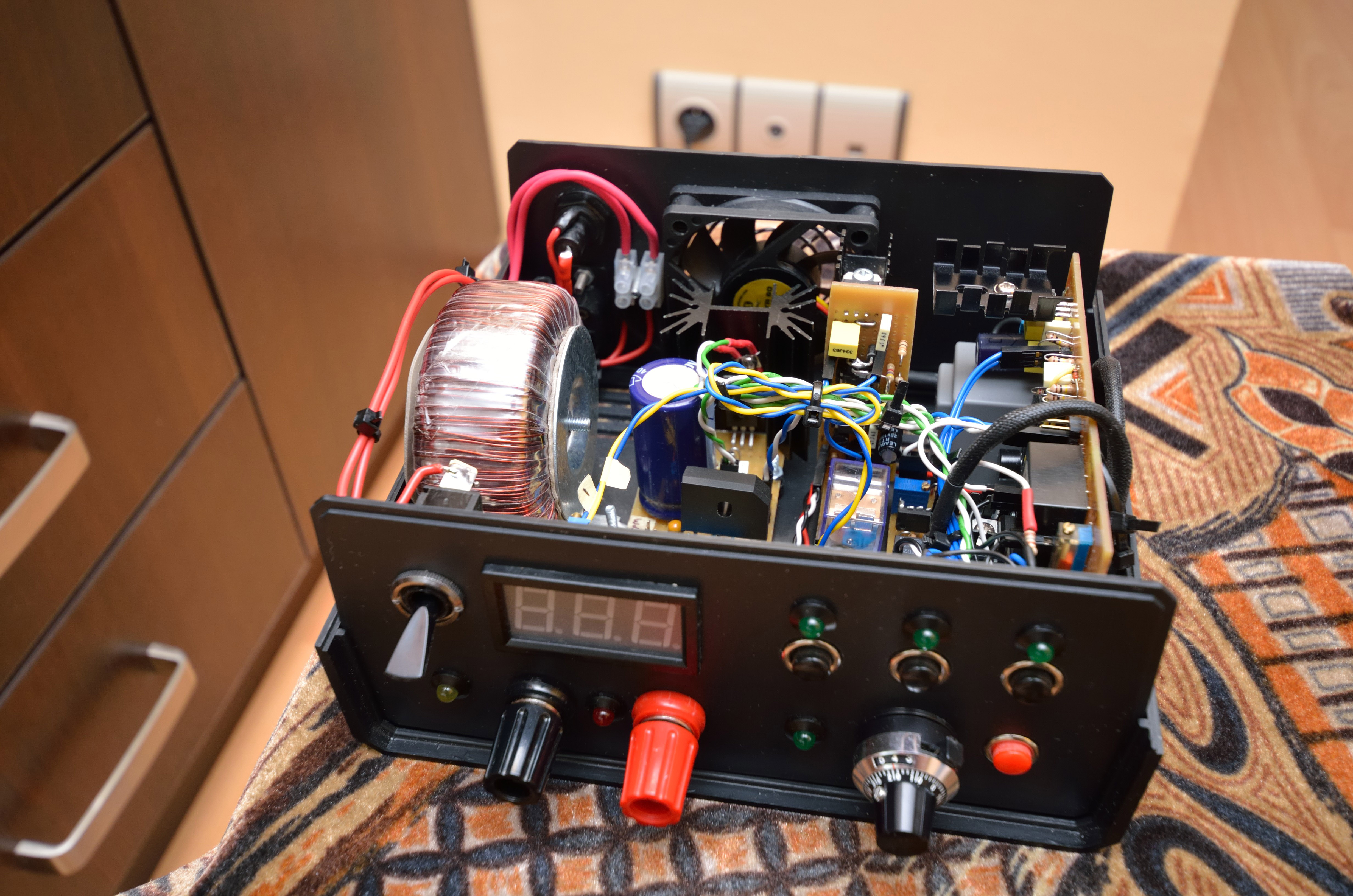
The power supply module is based on LM350 with additional ripple rejection capacitor. It is powered from toroidal transformer 50W 17V (20V without load).
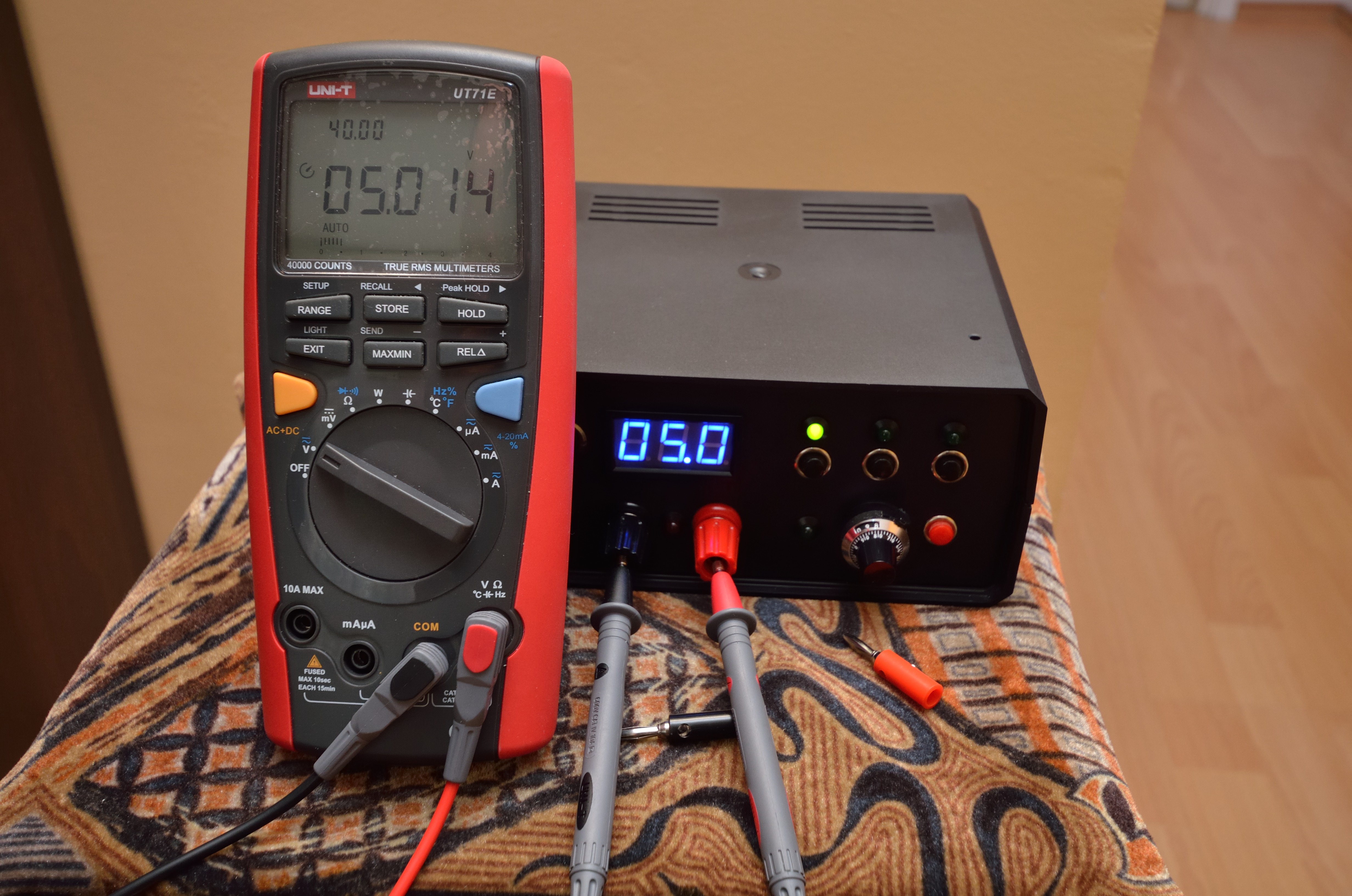
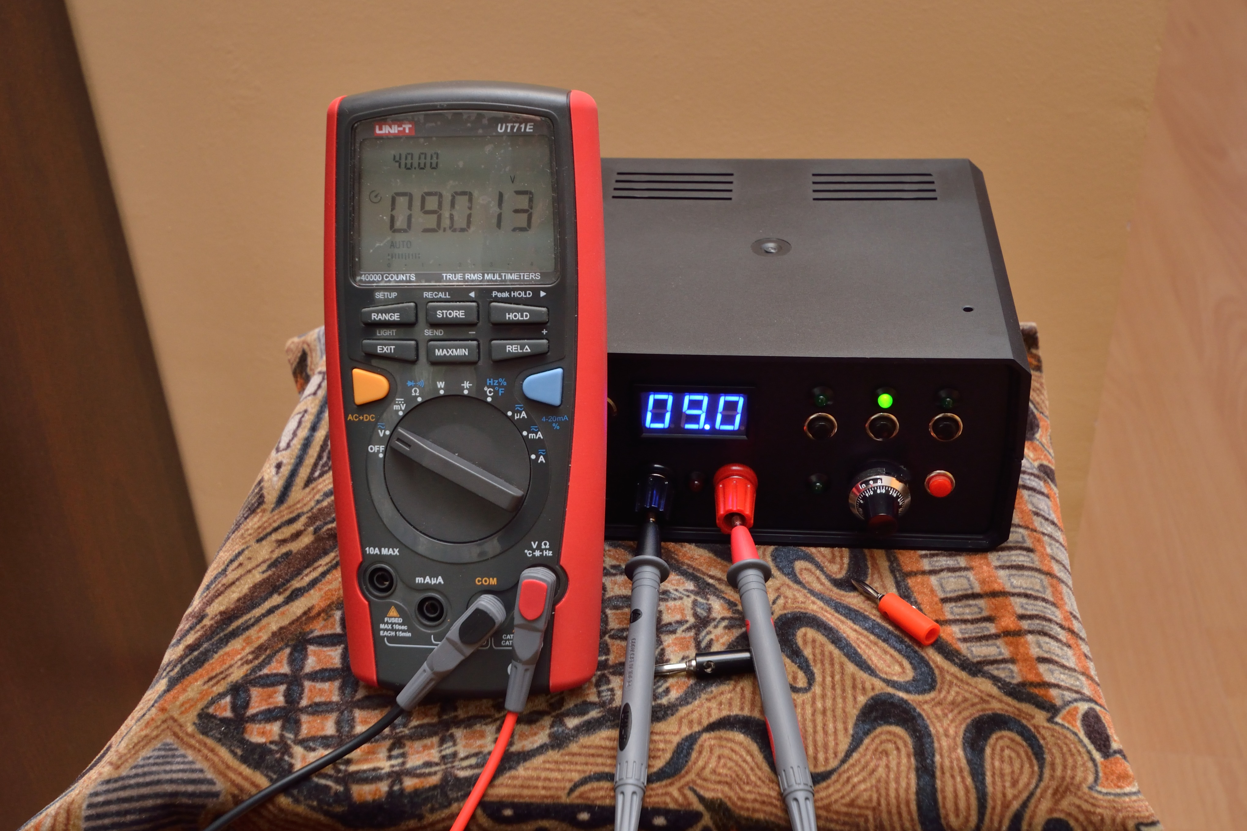
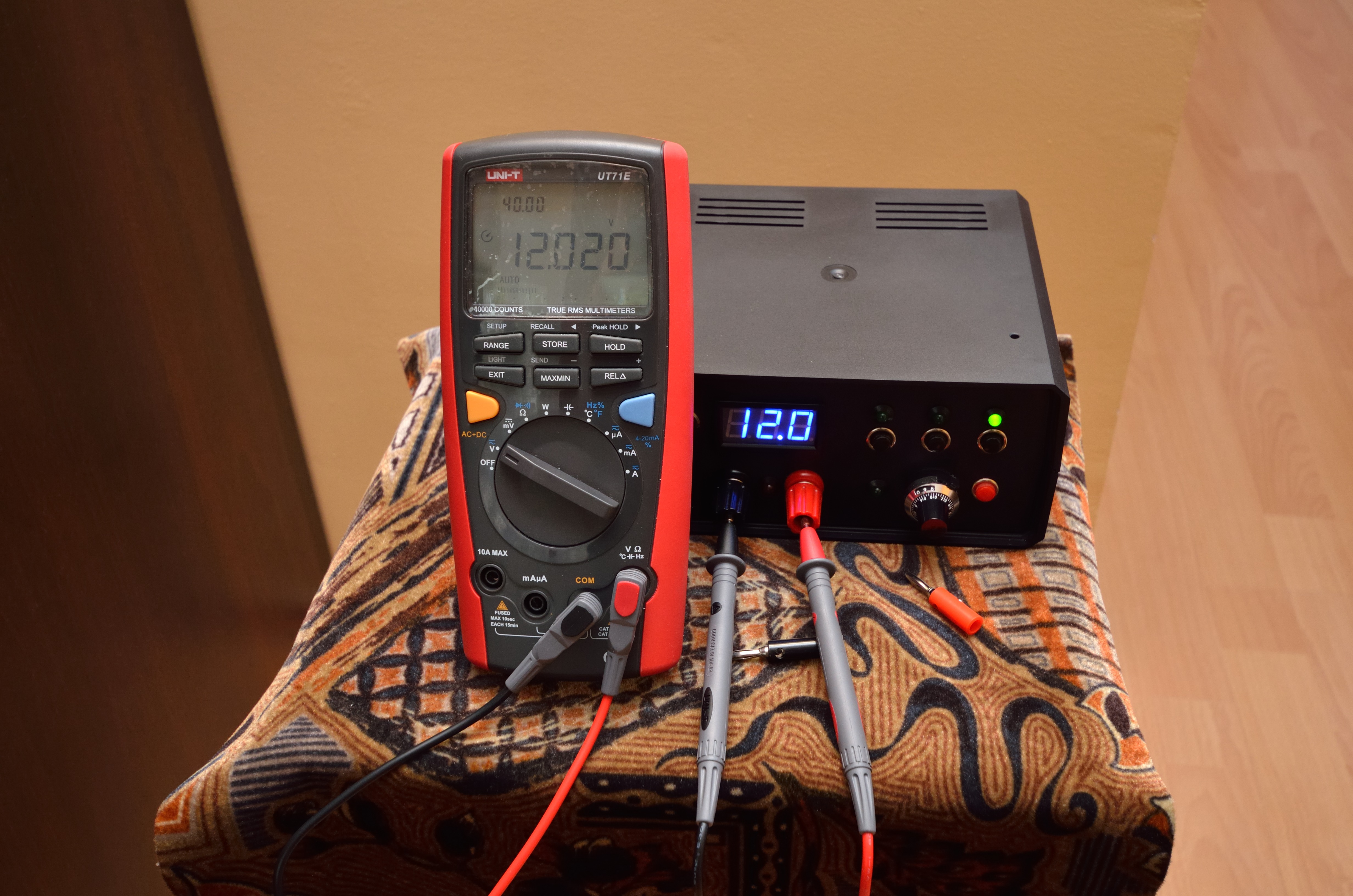
Voltage switching system is based on dependent switch system on 4042BE (previously it was used for switching light). It was applied to provide switching between three predefined voltages (5V, 9V, 12V) and to ensure smooth voltage regulation. When the power supply is switched on, the system activates the smooth voltage regulation what is indicated by green LED light next to the potentiometer. After pressing a black button, the LED above the button is turned on and the voltage corresponding to the button is activated (5V, 9V and 12V).
Short circuit indication system work consists of 3s beep and red LED lighting. The LED is placed between the output connectors. The system also uses a relay that disconnects the + from the clamp. The short circuit indication system is based on operational amplifier LM358 (as a comparator) and Timer 555.
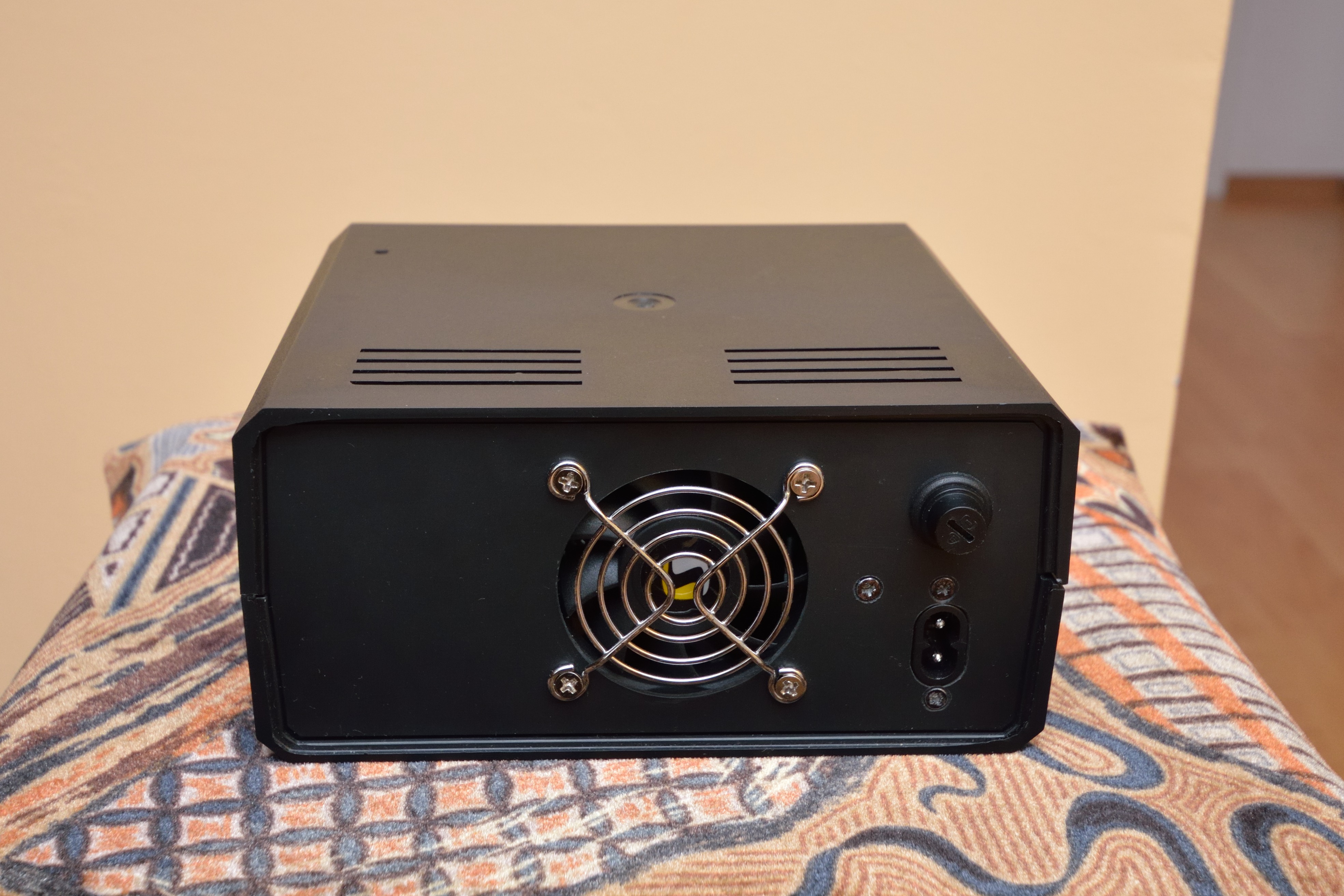
Thermostat was built using an operational amplifier and thermistor. When the set temperature of the heat sink is reached (in this case it is 39,7 degrees Celsius), the fan is activated and it cools down the heat sink by about 7 degrees Celsius. This scope of work is enough to cool the heat sink from the switch off threshold at a power consumption of 0,6A and operation voltage 12V. Fan operation is indicated by the yellow LED flashing. The yellow LED is placed on the left side under the switch.
Voltmeter uses LED. It is based on ICL7107 with a range of 0-99,9V. It is quite accurate, has aesthetic frame and what is the most important – it is cheap.
A multiturn potentiometer (10) with precise revolution counter is used for smooth voltage regulation. One revolution of the potentiometer changes the voltage by about 2,5V. The power supply allows the voltage regulation from about 1,3V to about 25V but it does not have the current limitation.
Pictures:
LINK
Link to original thread (useful attachment - schematics) - Zasilacz na LM350 z predefiniowanymi napięciami