Continue to Site

Welcome to EDAboard.com

Welcome to our site! EDAboard.com is an international Electronics Discussion Forum focused on EDA software, circuits, schematics, books, theory, papers, asic, pld, 8051, DSP, Network, RF, Analog Design, PCB, Service Manuals... and a whole lot more! To participate you need to register. Registration is free. Click here to register now.

Power supply/Inverter for EL panels .

Status
Not open for further replies.

raziev

Newbie level 3
Joined
May 9, 2013
Messages
4
Helped
0
Reputation
0
Reaction score
0
Trophy points
1,281
Activity points
1,313
Dear Members,

I have been working on Offline Inverter for EL panels (electroluminescent panels). EL panels are driven by 75 Volt AC and 1Khtz frequency. Main blocks of the design are
1. Mains AC (220 VAC 50Hz) to 150 Volt DC ( Flyback switch mode with secondary feedback)
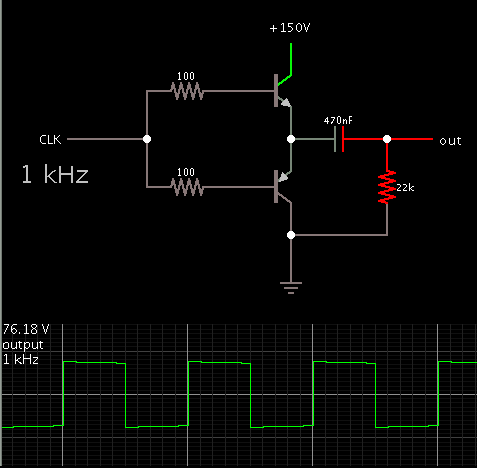
2. 150 Volt DC to 75 V AC ( half bridge inverter switching two mosfets with help of PIC)

A simple square wave is enough for EL panels, hence simple on/off of the switches is done at 1 KHZ and 50% duty cylce.

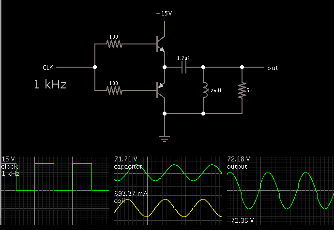
Now I am stuck-up with the output section of the Inverter - LC filter.

My questions are what are the considerations and calculations be done for deciding the values of L and C?
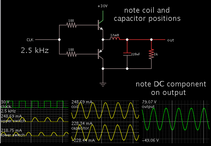
What are the functions of L? does it is used to only filter the harmonics or does it store the energy also?
My carrier frequency and out put frequency are same, how should I calculate the values of L and C?

I am a novice so please bear with me for any stupidity from my side.
Many Thanks
 

To get 75 V AC square waves from 150 V DC, you only need a capacitor to block the DC:

3990472300_1368101653.png


The resistor is needed at the output, so that the capacitor can charge and discharge.

Since your half-bridge already consists of the PIC and mosfets, you can disregard that part of my schematic.
 

Dear BradTheRad,

Thanks for the help, but I seen all the commercially available EL inverters with Toroidal Inductor in the out put section. The one I have has Inductor with 17 mH (toroidal with 330 turns on Sendust/Koolmu core ID-14mm, OD-30mm, Ht-11mm, inductance of core per turn2 is 157).
Does it used for energy storage or giving sinewave shape to output? or both?
If yes than, what are its design considerations?

Many Thanks

Adding a coil and capacitor can bring on resonating action. It can obtain sine waves from square waves.

The new amplitude can also be several times the supply V.

I made a broad assumption as to the arrangement of components. I started with a 17mH coil, then adjusted the capacitor value so as to boost the output V several times. Increasing the Farad value increases the output V, but it also draws more current from the supply. Only a few mA go through the load, hence its efficiency is low.


I don't know whether this is done in commercially manufactured units, but it certainly looks to be a handy technique. That is, if an EL display can be driven by sine waves.
 

Hi Brad,
It is done other way round coil is placed in place of capacitor and capacitor is parallel to load. Value of capacitor is 0.22uf.
Thanks
 

Hi Brad,
It is done other way round coil is placed in place of capacitor and capacitor is parallel to load. Value of capacitor is 0.22uf.
Thanks

I revised the simulation. It too turns square waves into sine waves, and at an amplitude greater than the supply V.

However a DC component is on the output waveform, since there is no capacitor blocking the DC.


The coil and cap values resonate at 2.5 kHz.

1k ohm as the load is a guess on my part. If it is changed then the resonant frequency changes too.
 

Hi Brad,
Is there any way to eliminate DC componet on the out put with out losing on efficiency?
Regards,
Rajeev
 

Hi Brad,
Is there any way to eliminate DC componet on the out put with out losing on efficiency?
Regards,
Rajeev

The straightforward technique is to put a DC blocking capacitor in series. That's the reason I arranged things as in post #4.

However if the manufacturer did it differently, there is probably a reason.

I don't know the specific way to drive EL panels, but if they are like an LCD display, they cannot tolerate a DC component in their driving AC waveform.
 

Status
Not open for further replies.

Part and Inventory Search

Welcome to EDABoard.com

Sponsor

Back
Top