Continue to Site

Welcome to EDAboard.com

Welcome to our site! EDAboard.com is an international Electronics Discussion Forum focused on EDA software, circuits, schematics, books, theory, papers, asic, pld, 8051, DSP, Network, RF, Analog Design, PCB, Service Manuals... and a whole lot more! To participate you need to register. Registration is free. Click here to register now.

Power supply for MGTAVTT (1.2 V) and MGTAVCC (1.0 V)

Status
Not open for further replies.

engr_joni_ee

Advanced Member level 3
Joined
Nov 3, 2018
Messages
750
Helped
2
Reputation
4
Reaction score
4
Trophy points
18
Activity points
6,232
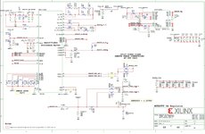
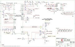
I am working on power supply for the FPGA board and found the schematic for MGTAVTT (1.2 V) and MGTAVCC (1.0 V). Both are 5 A power supplies. This look like a complex design in the attached schematic. I am wondering if we can also use other regulator for both MGTAVTT (1.2 V) and MGTAVCC (1.0 V) ?

In order to understand these power supplies. I will have several questions. Can someone please help me by explaining the attached schematic with the function of each pin doing ?
 

Attachments

  • Screenshot_20230106_181044_Chrome.jpg
    Screenshot_20230106_181044_Chrome.jpg
    168.2 KB · Views: 148
  • Screenshot_20230106_181035_Chrome.jpg
    Screenshot_20230106_181035_Chrome.jpg
    167 KB · Views: 140

One question about MGT power supplies. Do we need just a source or source/sink for MGT power supplies. If it is only source then other choices for 1V @5A and 1.2V @5A can be used instead.
 

Hi,

Theoretically you may use any kind of power supply, as long as it meets the load requirements.
Especially
* voltage accuracy
* resonse on load current jumps

Now ASICS/FPGAs may cause rather fast jumps in supply current ... in the picoseconds range. The correct placement and choice of the bypass capacitors is the first step (but extremely important) to a reliable supply.

When you talk about "other supplies" I guess you think about linear supplies instead of SMPS.
5V to 1V? So you "waste" 4V (multiplied with current) and thus generate a lot of heat. Most probably you need a big heatsink with a fan. And it needs to be able to handle not only the fast response but also the high capacitive load with low ESR. Not an easy task.

There is a good reason to do it the way they do.

Klaus
 

Now I have a specific question. I have attached two power supplies in the first post, one for MGTAVCC (1.0 V @ 5 A), and one for MGTAVTT (1.2 V @ 5 A).

Calculation for MGTAVCC (1.0 V @ 5 A):

Number of populated phase = 1, because only ISENSE2 along with PMW2 are connected to slave device which is one-phase according to Table 2. Phase Population Position.

RSEL3 = 80.6 Ohm (Fsw = 600 KHz and slew rate = 1.25 V /ms)
RSEL2 = 402 Ohm (Vout = 0.030 V)
RSEL1 = 576 Ohm (Vout = 0.970 V)
RSEL0 = 0 Ohm (RDES = 640 Ohm)

Vout = 0.030 + 0.970 = 1 V
Ioutmax = 0.85 x Iocp

Iocp from Table 5 for RDES = 640 Ohm and one-phase is 25 A that gives Ioutmax = 0.85 x 25 = 21.25 A but in the schematic it says 5 A. How they calculate 5 A ?

Calculation for MGTAVTT (1.2 V @ 5 A):

Number of populated phase = 1, because only ISENSE2 along with PMW2 are connected to slave device which is one-phase according to Table 2. Phase Population Position.

RSEL3 = 1020 Ohm (Fsw = 800 KHz and slew rate = 0.5 V /ms)
RSEL2 = 576 Ohm (Vout = 0.030 V)
RSEL1 = 1020 Ohm (Vout = 1.170 V)
RSEL0 = 0 Ohm (RDES = 640 Ohm)

Vout = 0.030 + 1.170 = 1.2 V
Ioutmax = 0.85 x Iocp

Iocp from Table 5 for RDES = 640 Ohm and one-phase is 25 A that gives Ioutmax = 0.85 x 25 = 21.25 A but in the schematic it says 5 A. How they calculate 5 A ?
 

If you really want answers, you should post readable schematics rather than blurry screenshots.

ISENSE scaling depends on the slave switcher device(s) used in the circuit. Unfortunately I can't read the part number.
 

I have attached the schematic in which they use MAX20751. Kindly have a look at my questions at post # 5.
 

Attachments

  • KCU105-Schematics 58.pdf
    100.4 KB · Views: 177
  • KCU105-Schematics 59.pdf
    100.5 KB · Views: 93
  • max20751.pdf
    3 MB · Views: 92

The power supply is designed for 5A, limited by the current monitor range and probably also by output inductor rating. You can check Xilinx KCU105 BOM if you are interested in details.

Iocp is actually much higher. I guess the designer has simply selected the lowest range specified in MAX20751 datasheet instead of calculating new component values.
 

Hi, I am not sure what do you mean by current monitor range. I am also not getting what is VT1697SBFQX doing in the circuit. If Iocp is higher then it is in the higher range not lower, right ?

Which inductor rating you are mentioning L70 and L71, or any other ?
 

Hi, I am not sure what do you mean by current monitor range.
KCU105 has current measurement for all power supply rails. You'd know if you read user manual and schematic thoroughly.
I am also not getting what is VT1697SBFQX doing in the circuit.
It's output power stage, well explained in datasheet, I think.
Which inductor rating you are mentioning L70 and L71, or any other ?
Both power supplies have same current rating. Guess they are using the same output inductor.
 

If we say that the external inductor is limiting the output current than it's fine but the chip MAX20751 itself has Ioutmax = 0.85 x 25 = 21.25 A right ? given the external resistors RSELx.
--- Updated ---

Th formula for Ioutmax is given in max20751 datasheet on page 20 which is t IOUTMAX = 0.85 IOCP. The calculation of IOCP is 25 A, given the external resistors RSELx.
 
Last edited:

Hi, I have asked this question already some months before on EDABoard but then found some mistakes in my calculations. I am sorry about confusion. After correction I am posting this question which is about understanding and using power supplies MGTAVCC (1.0 V @ 5 A) MGTAVTT (1.2 V @ 5 A) in the Kintex Ultrascale development board KCU 105. The relevant pages from schematic for power supplies MGTAVCC (1.0 V @ 5 A) MGTAVTT (1.2 V @ 5 A) are attached along with the datasheet of MAX20751.

The specific question regarding MGTAVCC (1.0 V @ 5 A), and MGTAVTT (1.2 V @ 5 A).

Calculation for MGTAVCC (1.0 V @ 5 A):
Number of populated phase = 1, because only ISENSE2 along with PMW2 are connected to slave device which is one-phase according to Table 2. Phase Population Position of MAX20751 datasheet.
RSEL3 = 80.6 Ohm (Fsw = 600 KHz and slew rate = 1.25 V /ms) found from Table 6. Using R_SEL3 to Set the VOUT Slew Rate and Switching Frequency of MAX20751 datasheet.
RSEL2 = 402 Ohm (Vout = 0.970 V) found from Table 7 of MAX20751 datasheet.
RSEL1 = 576 Ohm (Vout = 0.030 V) found from Table 7 of MAX20751 datasheet.
RSEL0 = 0 Ohm (RDES = 604 Ohm) found from Table 7 of MAX20751 datasheet.

Vout = 0.030 + 0.970 = 1 V
Ioutmax = 0.85 x Iocp found from Table 5 of MAX20751 datasheet.

Iocp from Table 5 with RDES = 604 Ohm and one-phase is 25 A that gives Ioutmax = 0.85 x 25 = 21.25 A but in the schematic it says 5 A. How 5 A is calculated ?
PMAD [2:0] : 010: Please check and confirm the PMBus Address Bits ?
Do we need to mount RDES physically in the circuit, if yes then where. I don't found it in the KCU 105.

Calculation for MGTAVTT (1.2 V @ 5 A):
Number of populated phase = 1, because only ISENSE2 along with PMW2 are connected to slave device which is one-phase according to Table 2. Phase Population Position of MAX20751 datasheet.
RSEL3 = 1020 Ohm (Fsw = 800 KHz and slew rate = 0.5 V /ms) found from Table 6. Using R_SEL3 to Set the VOUT Slew Rate and Switching Frequency of MAX20751 datasheet.
RSEL2 = 576 Ohm (Vout = 1.170 V)
RSEL1 = 1020 Ohm (Vout = 0.030 V)
RSEL0 = 0 Ohm (RDES = 604 Ohm)

Vout = 0.030 + 1.170 = 1.2 V
Ioutmax = 0.85 x Iocp

Iocp from Table 5 with RDES = 604 Ohm and one-phase is 25 A that gives Ioutmax = 0.85 x 25 = 21.25 A but in the schematic it says 5 A. How 5 A is calculated ?
PMAD [2:0] : xx0 ? Please check and confirm the PMBus Address Bits ?
Do we need to mount RDES physically in the circuit, if yes then where. I don't found it in the KCU 105.
 

Attachments

  • max20751.pdf
    3 MB · Views: 71
  • KCU105-Schematics 59.pdf
    100.5 KB · Views: 143
  • KCU105-Schematics 58.pdf
    100.4 KB · Views: 71

Status
Not open for further replies.

Similar threads

Part and Inventory Search

Welcome to EDABoard.com

Sponsor

Back
Top