Vermes
Advanced Member level 4
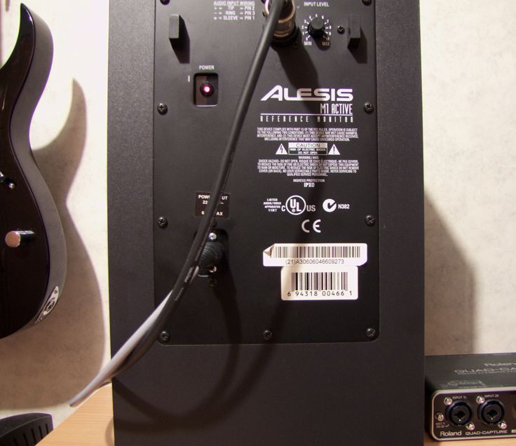
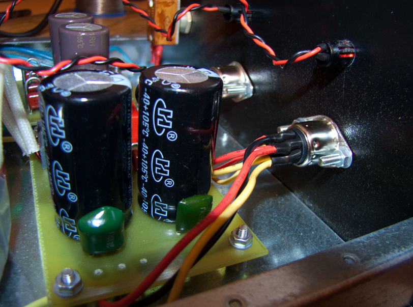
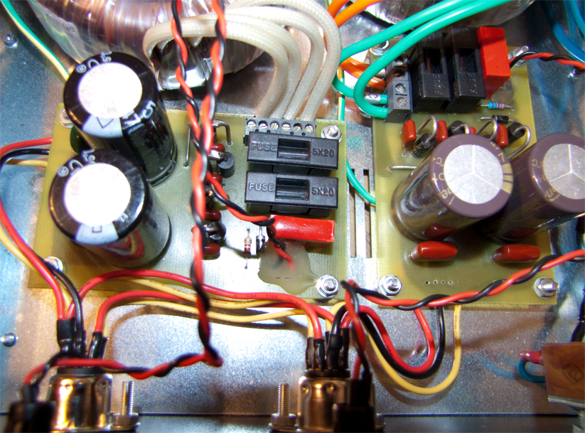
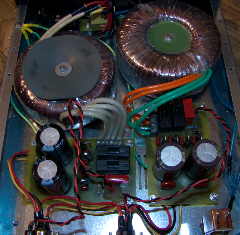
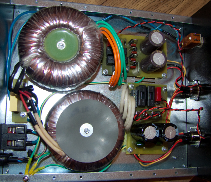
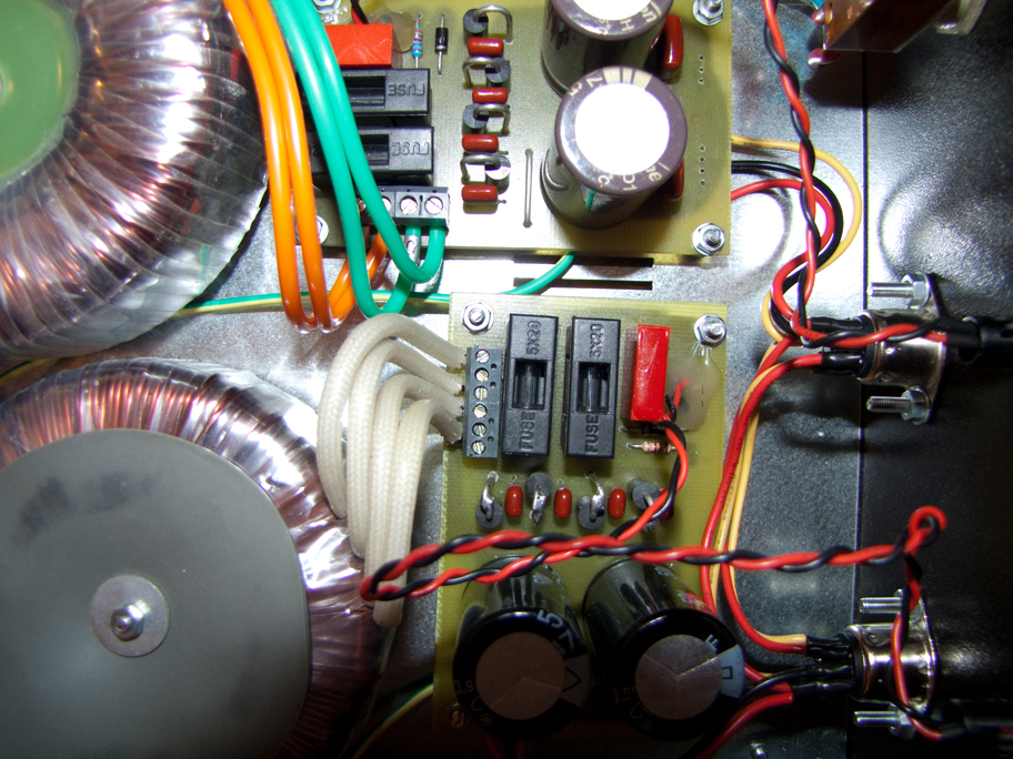
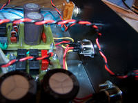
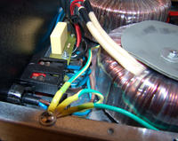
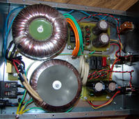
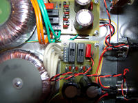
It is a construction of classic inner power supply for ALESIS M1 Active Mk2 speakers with broken pulse power supplies. Schematic of the power supply is simple – instead of bridges, there are diodes bypassed with capacitors. There is a simple filter made of capacitors on the primary side.
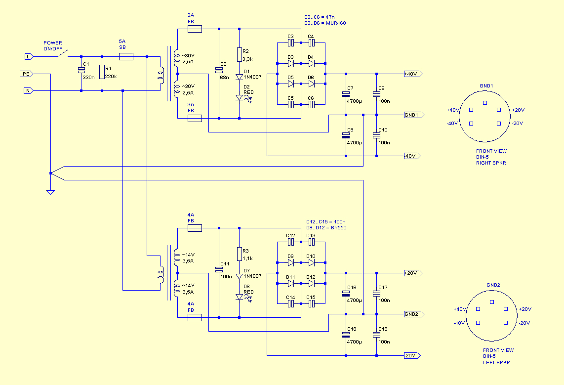
In the original, each pwoer amplifier in the speaker is powered with two voltages:
- +/-36V (2x 1A) for LM3886, which powers the woofer
- +/-18V (2x 1A) for LM2876, which powers the tweeter
[/list[
Transformers used were: 2x ~ 30V (2x 2,5A), which gives +/-42V on idle and 2x ~ 14V (2x 3,5A) which gives +/-20V on idle.
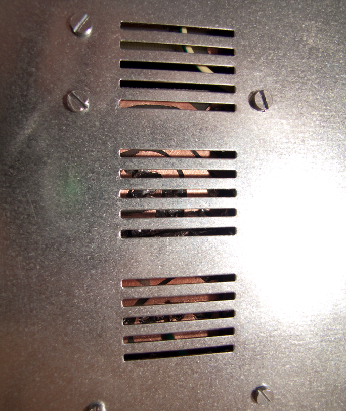
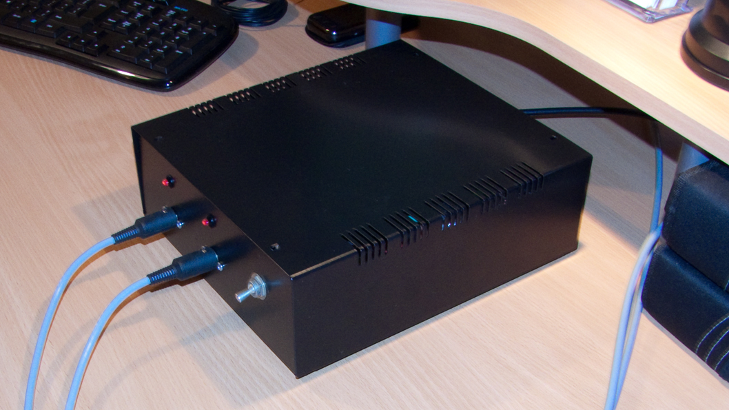
Blue diodes (3mm) on the front of the housing were disconnected. Instead of them, there are simple red LEDs indicating turning on of the speaker. They are put in place of mains switches on the back of the housing.
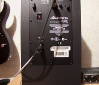
Due to the significant number of voltages, they are derived to the speakers by 6-wires cable, plugs are well-known DIN-5. DIN-5 sockets are LEDs in speakers were mounted on boards of plexiglass, which were painted black form the inside. Boards for LEDs were mounted with a black silicone glue. DIN-5 sockets were screwed with M3 screws in place of IEC 230V socket.
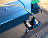
Pictures:


Link to original thread - Zasilacz do kolumn ALESIS M1 Active Mk2