Continue to Site

Welcome to EDAboard.com

Welcome to our site! EDAboard.com is an international Electronics Discussion Forum focused on EDA software, circuits, schematics, books, theory, papers, asic, pld, 8051, DSP, Network, RF, Analog Design, PCB, Service Manuals... and a whole lot more! To participate you need to register. Registration is free. Click here to register now.

Power supply for ADC chip Analogue Grounding Question

userx2

Full Member level 3
Joined
Sep 19, 2008
Messages
168
Helped
2
Reputation
4
Reaction score
3
Trophy points
1,298
Activity points
3,022
Hello,

I am just designing the power circuit for a 24bit ADC chip interfacing to a microcontroller on the same PCB.
The manufacturer recommends separate regulators for the digital and analogue side. Fair enough.
But I am confused about the grounding configuration.
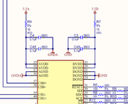
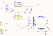
I thought the output caps of the analogue (3.3A) regulator should go to AGND but in this circuit, they have connected then to the Digital GND.

The ADC chip AGND pins and local decoupling caps are the only parts connected to the AGND.

Is that correct and what would be the reasoning behind that configuration?
Please see picture

Best regards
X
 

Attachments

  • Analog Voltage Ground1.png
    Analog Voltage Ground1.png
    38 KB · Views: 36
  • Analog ADC Grouind 2.png
    Analog ADC Grouind 2.png
    55.4 KB · Views: 37
Hi,

just to clarify: with AC excitation you are able to measure frequencies down to DC. This is not the same as AC coupling i.e. HighPassFiltering.

DAC as offset correction will work, also a digital pot. The digital pots may be "non volatile" thus may be factory calibrated. No need for multiple calibrations. (like at every power up). This may be beneficial or not.

We don't know enough about the application to determine if hardware sensor calibration is feasible. It's however obvious that resolution at 25 S/s will be noise limited. A detailed calculation is necessary as design starting point.
True.
Regarding noise the ADC is not that bad (cosidered the low cost) .. since due to internal digital filters it takes up to 1024 (if I remember right) individual samples into account.

Calculation is necessary, I agree. But in this case I also consider to run an FFT over the sampled values to distinguish between true noise and introduced foreign frequencies (they may be filtered out in first place).

***

Yes, filtering. If you go far a data rate (*) of 25 smpl/s Then you may apply external HPF with a corner frequency of 12Hz.

In either case proper signal filtering and clean sensor supply is essential to get best quality informations.

****
(*) especially here I want to differ between sampling rate (conversion rate) and data rate. For the given ADC and a data rate of 25 smpls/s (data/s) the true sampling rate is much much higher, depending on ADC OSR setup.

Klaus
 
A multi channel approach, one chip, could look like this part, a SOC :

1715250155771.png


Whats onchip, multiple copies in most cases, like 4 OpAmps, 4 DACs, 1 DelSig, 2 SAR, and all the rest ...

1715250265505.png


Each of the above, in PSOC language, is considered a "component", and has a rich set of APIs user
uses for configuration and control. Eg. rare you write a driver.

IDE (PSOC Creator) and Compiler free. Dev boards for ~ $20 and up (depends on how much I/O
and other features you want).

PSOC 5LP family has Arm M3 core on it.

Also has digital filter block on it :

1715250785041.png


This is config wizard for it :

1715250908227.png


Regards, Dana.
 
Last edited:
Hi,

Dana, I´ve seen you several times to recommend these SOCs.
I´ve zero experience with them. (indeed I´m a bit curious)

Can you give a short information how they compare in analog performance (OPAMPs) as well as ADC performance (noise / ENOB, drift...)
Best when you could compare to the given ADC .. or even better when referenced to the OP´s application.

I don´t expect an entire datasheet, nor high effort in maths and so on ... just a couple of lines of general information or your experience.

Klaus
 
@dana, interesting, I will look into it.

@KLAUS, I looked at digital potentiometers earlier today but I could not see a continuous o or highbresolation one. They mostly havec 32 to 64 steps and only spme have 256 steps. It was not enough to get the offset close enough to 0 to still have signal range at gain 1500.

The idea of Eeprom pot is good but if this ends up using a MUX followed by all single channel circuitry, the offset has to change for each sensor as selected.
I do not know yet.
--- Updated ---

@userx2 Sounds like you don't understand the concept of AC excitated (carrier frequency) strain gauge.
You are correct, I do not know anything about that yet.
However, one other complication is that the sensor in question is somewhat electronic. It has the bridge inside, an enable pin and according to the block diagram also a buffer on S+ as well as S-.
If AC excitaion means changing the power to the bridge, then I don't think that will work here.

Bestvregards
X
 
Last edited:
Hi,

Dana, I´ve seen you several times to recommend these SOCs.
I´ve zero experience with them. (indeed I´m a bit curious)

Can you give a short information how they compare in analog performance (OPAMPs) as well as ADC performance (noise / ENOB, drift...)
Best when you could compare to the given ADC .. or even better when referenced to the OP´s application.

I don´t expect an entire datasheet, nor high effort in maths and so on ... just a couple of lines of general information or your experience.

Klaus
The OpAmps are, in my opinion, LM324 kinds of parts, RRIO. See attached.

The DelSig, although 20 bits, effectively 16 bits, due to INL limitations. See attached. Res down
to ~ 1 uV at 16 bits using input buffer G set to 8. May be usable when noise is looked at using
the double correlated sampling approach posted earlier. OP has to examine total requirements/
tradeoffs. 20 bits might be achievable thru production test cal routine.......power curve fit kind of
approach, would have to be examined via characterization qual if T and V dont corrupt the fit,
are well behaved....

Onboard Vref good to +/- .1%......room temp, have to look at table for temp extremes.


Regards, Dana.
 

Attachments

  • ADC_DelSig_v3_20.pdf
    1.2 MB · Views: 19
  • OpAmp_v1_90.pdf
    449.3 KB · Views: 20
Last edited:
Hi Dana,

I am going to look into the SOC you mentioned. SOC = System on Chip ?

My search shows that SOC Creator as in you pictures is an Infinion product.

If you have any recommendations on where to start / dev kit etc, please share.

Best regards
X
 
Board to start with : https://www.infineon.com/cms/en/product/evaluation-boards/cy8ckit-059/ There are
boards with a lot more I/O, and cost more, but this is an excellent low cost starter board.

Tool : https://softwaretools.infineon.com/...04.178471112.1715293948-2138762758.1715293948

PSOC was a Cypress company, purchased recently by Infineon.

SOC is System on a Chip.

The IDE has many projects you can download, cut and paste from. Additionally there are these
resources :


https://github.com/Infineon/PSoC-4-BLE/tree/master/100_Projects_in_100_Days BLE

The community has done some of their own components designs that can be imported into
the IDE. Creator allows one to use schema capture and/or Verilog to design your own specialized
reusable components for the lib. Like DDS, some 74HC type MSI logic components, CPLD, CORDIC
.....I can send those to you if interested.

Regards, Dana.
 

LaTeX Commands Quick-Menu:

Similar threads

Part and Inventory Search

Welcome to EDABoard.com

Sponsor

Back
Top