Continue to Site

Welcome to EDAboard.com

Welcome to our site! EDAboard.com is an international Electronics Discussion Forum focused on EDA software, circuits, schematics, books, theory, papers, asic, pld, 8051, DSP, Network, RF, Analog Design, PCB, Service Manuals... and a whole lot more! To participate you need to register. Registration is free. Click here to register now.

Power Supply for a 150+150W Amplifier

Status
Not open for further replies.

dvijaydev46

Newbie level 4
Joined
Jan 23, 2013
Messages
6
Helped
0
Reputation
0
Reaction score
0
Trophy points
1,281
Activity points
1,318
Hi,

I'm planning to build this amplifier https://www.circuitstoday.com/150-watt-amplifier-circuit . Since I'm going to make a stereo amp, I need to double the power rating of the power supply given there and here. I would like to know the following:

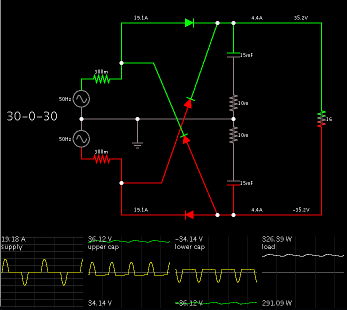
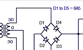
1. Should I go with a 30-0-30 10amp or 12amp transformer?
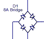
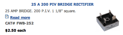
2. What diode should I use for the bridge? (please recommend a 15amp diode)
3. Can I use two P600A diodes in parallel for the bridge?

Thanks
Vijay
 
Last edited:

Hello,
Using two diodes in parallel is not a good idea. Your diodes are not perfectly identical physically. The diode which has the smaller drop (0.6volt or less for a shotkky) will transfer all the power...
 

Hi Gozaki,

even I was thinking of the same. Could you please recommend a 12A to 15A diode of at least 50v?
 

Thanks for the link. looking into it but seems to be confusing. Is there any particular diode that works at the volt and current range I have given?
 

Your diodes will be exposed to bursts of 19 A, according to my simulation.

Screenshot:


I took the snapshot when two of the diodes are conducting maximum current.

The website gives three different volt levels supplying the amplifier. If you go with a 30-0-30 transformer, it will deliver peaks of 42 V. My simulation shows the resulting supply is 35V at full load. This may drop further depending on your transformer's internal resistance. (I represented this resistance as .3 ohm in each of the two secondary windings.)

For the two stereo channels I decided to depict them as a load of 16 ohms total. This equates to an 8-ohm speaker getting 50% duty at positive polarity and 50% duty at negative polarity. That's like a constant 16 ohms at top, constant 16 ohms at bottom, in series. Add a second channel in parallel. That works out to a 16 ohm total load.

The watt output is in the ballpark of what you want.
 

Hi BradtheRad,

Thanks for the detailed reply. I don't understand one thing. Do you mean to say that I need to add a second rectifier?

Thanks
Vijay
 

Hi BradtheRad,

Thanks for the detailed reply. I don't understand one thing. Do you mean to say that I need to add a second rectifier?

Thanks
Vijay

You'll need 4 diodes... either separate, or packaged in a bridge rectifier.

The schematics at circuitstoday.com are not consistent in the way they label the diode bridge. It's no problem. This type of power supply is very common, and easy to construct.

One of the schematics labels the bridge rectifier 'D1' although it contains 4 diodes.

9597247600_1359003655.png


The other schematic shows 4 diodes labelled D1-D5. Maybe D5 is supposed to be the bridge rectifier package, and it's simply tacked onto the list... because I don't see a fifth diode in the schematic.

4299406700_1359003438.png


My simulation shows each diode conducts 19A at a duty cycle of about 15 percent. This is an average of 3A continuous. Nevertheless you should use a bridge rectifier rated to handle 19A.
A 15A rating may be sufficient, but you would be taking a chance. (Remember that powerup surge current can be high.)

The 4-diode package will heat up as a result of dissipating 7 W average power.

Thanks. Since I'm not able to find a suitable diode that can handle 20A of current which can be soldered to a PCB, I have decided to get a bridge rectifier of 20A 100V. Anyway, I'll etch a new PCB to accommodate the bridge rectifier. Thanks all for your help.
 

I have decided to get a bridge rectifier of 20A 100V. Anyway, I'll etch a new PCB to accommodate the bridge rectifier.

That rating is adequate. I can't be sure how much heatsinking it will need, so I can't advise about mounting it on a PCB.

Below is a shot of a suitable bridge rectifier available from All-Electronics (a mail-order electronics house I have dealt with).


7374623300_1359011460.png
 

Thanks. I'll make the PCB after deciding on the size of the heat sink.
 

Status
Not open for further replies.

Part and Inventory Search

Welcome to EDABoard.com

Sponsor

Back
Top