Welcome to our site! EDAboard.com is an international Electronics Discussion Forum focused on EDA software, circuits, schematics, books, theory, papers, asic, pld, 8051, DSP, Network, RF, Analog Design, PCB, Service Manuals... and a whole lot more! To participate you need to register. Registration is free. Click here to register now.
Yes you can simulate that to demo the point.
Those diodes aren’t necessarily only for parallel smps, they can be used with a single smps.
Its just that when an smps goes into no-load, its error amplifier tends to rail low…..the error voltage just plummets all the way down to the rail…..this is a problem when it is subsequently suddenly loaded, because the compensation capacitors then need charging up a lot further in order to get the smps into regulation, so all the diodes do is stop the error amplifier railing in no-load.
So basically it stops the compensation capacitors from charging/discharging too much, then taking too much time to get back into the zone of regulation.
Those diodes are always a good idea, but often people just don’t bother with them, and just tolerate a large vout undershoot following a no-load-to-full-load transient.
Be sure to get the diodes the right way round though
- - - Updated - - -
by the way, parallel smps's that regulate vout need either current sharing circuits, or they must use the same error amplifier for feedback
Thank you Treez
Will you please clarify your line "Be sure to get the diodes the right way round though" Do you mean the The right polarity?
We do have current sharing circuit we need this diode to help for first 80ms or so during transient
ok, well here is the rendition of that diode that I have seen used, it means that the error amplifier output voltage doesn't have to transition so far in order to "brake" the smps at start up...so yes it helps to reduce overshoot of vout at startup.
-its ltspice simulation and pdf
- - - Updated - - -
I don't believe that the diodes are related to the paralleling though.
Your current sharing circuitry is what deals with the paralleling.
As you say, the diodes are to reduce overshoot on transients such as startup.......its to stop the error amp voltage going to the rail.
- - - Updated - - -
And also, so that you can see the full operation of the diode, and the comparison with NOT using it, the attached simulation called "synchronous buck_overshoot reduction" compares it with and without the diode
thank you Treez
I am confused about diode direction
Will the ltspice schematics prevent the output of error amp going too low.That is condition i want to prevent.The lt-spice arrangement only help output overshoots.
I arranged it more like a buffer to prevent the output not going no more than two diode drop from reference voltage(Non-inverting input).Is there any thing wrong with that(my arrangement), simulation and test results looks good but i want to make sure , is there anything I am missing?
The diodes have to be in there so that they stop the error amp from saturating so far, but the right way round so that they don't stop the smps from being able to go to full load , or alternately, completely stop pulsing the fet so that no power goes to the output in no load.
I hope I explained that well enough. In other words, the diodes shouldnt stop normal operation.
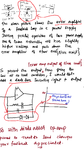
Diodes at the OPAMP feedback.
...Opamps are made for liniear operation. That meabs both inputs have (about) the same level and the output is not saturated.
But without the diodes the output sometimes is saturated, and thus, like treez wrote it takes some time to charge the feedback capacitors.
But not only the output gets saturated, the input stage of the opamp also.
The input stage, when saturated needs some time go get back in linear operation, it's a little time latched up. (It's increased delay even without external capacitors)
Some opamps don't like saturated situation. Some even reverese the output voltage (phase reversal) wich often leads to a very critical situation.
Diode orientation:
What direction the diod needs depend on the direction you e pect the saturation.
From your picture ut is not clear to me if you expect the Opamp to saturate on the high side or low side.
If high side: anode is at the output
Sometimes a simple silicon diode is sufficient, but sometimes you need a diode+zener combination.
This depends on the voltage level of the inverting input and the desired voltage level at the output.
This site uses cookies to help personalise content, tailor your experience and to keep you logged in if you register.
By continuing to use this site, you are consenting to our use of cookies.