Continue to Site

Welcome to EDAboard.com

Welcome to our site! EDAboard.com is an international Electronics Discussion Forum focused on EDA software, circuits, schematics, books, theory, papers, asic, pld, 8051, DSP, Network, RF, Analog Design, PCB, Service Manuals... and a whole lot more! To participate you need to register. Registration is free. Click here to register now.

[PIC] Power factor measurement using PIC18f4520

Status
Not open for further replies.
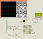
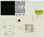
If I substitute 7 for the variable count and do the calculation then it shows exact result but I don't know why it is failing in getting the proper value for the count variable. Am I doing something wrong with Proteus ? The Proteus Oscilloscope shows that the difference between the 1st signals ZC and 2nd signals ZC is 7 ms and for 7 ms there should be 7 x 4 = 28 (250 us) timer interrupts but all the time it is showing 11 or 12.
 
This is where I start shouting curses at Oshonsoft! The simulator is far too slow to check these things will work in real life. There is also no way to add a breakpoint at a particular place in the source code, you have to find the equivalent assembly line and put it there and worst of all, if you single step the BASIC instructions, there is no way to make it resume full speed again, you have to reset it to the start. To be fair to them, when it does work, the code it produces is very compact but they should concentrate on core functionality rather than making it look pretty.

Anyway, rant over! The fact that you see different figures is encouraging, it means the timer is actually counting different numbers when the phase changes. I wuld not expect a true phase value at this stage becuase the result is only a time measurement, it has to be scaled to represent 0 - 180 degrees then the cosine taken to show the real phase.

The LCD problem is due to the interrupts being processed faster than the LCD routines can show the results. What is happening is the LCD commands do not have time to finish before the next data is being written to them. When you see a partial line of characters, it is because the 'home' command was used before the previous line was fully displayed.

The important point here is that the actual measurement must be accurate, how it displays it is of secondary importance. One way to do it would be to place the LCD routine inside the interrupt so it has to finish displaying before it can take the next measurment but that would be considered very bad practise because it would not only block further timer interrupts but any other interrupt you tried to use as well.

The alternative is not to re-enable the timer interrupt until after the LCD routines have finished. This has the drawback that there is a (tiny) period between enabling the interrupt and the next instruction being processed where an interrupt could sneak in. Without intimate knowledge of the compiler output it's difficult to avoid it.
Try this change, it should fix the LCD problem but do not expect to see the phase as the result yet, a fairly steady number is what I would like to see:
Code:
loop:
'phase = timer / scale_factor
		Lcdcmdout LcdLine1Home
		Lcdout "count = "
		Lcdout #timer
		INTCON3.INT1IF = 0
		T1CON.TMR1ON = 1
	Endif

Goto loop

End                                               

On High Interrupt
'If INTCON.INT0IF = 1 Then
'T1CON.TMR1ON = 1
'INTCON.INT0IF = 0
'Endif

	If INTCON3.INT1IF = 1 Then
		T1CON.TMR1ON = 0
		timer = (TMR1H * 256) + TMR1L
		TMR1H = 0
		TMR1L = 0
	Endif
Resume

Brian.


Dear Brian,

They've accepted the petition of switching from Oshonsoft to mikroC PRO for PIC.

After declaring results, and bug in Oshonsoft, they got convinced, but I still have to encounter a -10% curve down from the total grade, for braking syllabus rules.

That's not a major problem.

by referring to pic.programmer codes on mikroC PRO, here's what he has found concerning the power factor measurement:

Code:
#include "float2ascii.h"

unsigned long delta = 0;
char myFlags = 0, str[32];
double count = 0.0, time = 0.0, angle = 0.0, powerFactor = 0.0, powerFactorPrevious = 0.0;
unsigned int degree = 0, minutes = 0, seconds = 0;
const char character[] = {6,21,21,21,14,4,4,4};

sbit process at myFlags.B0;


#define _LCD_FIRST_ROW          0x80     //Move cursor to the 1st row
#define _LCD_SECOND_ROW         0xC0     //Move cursor to the 2nd row
#define _LCD_THIRD_ROW          0x94     //Move cursor to the 3rd row
#define _LCD_FOURTH_ROW         0xD4     //Move cursor to the 4th row
#define _LCD_CLEAR              0x01     //Clear display
#define _LCD_RETURN_HOME        0x02     //Return cursor to home position, returns a
                                         //shifted display to its original position.
                                         //Display data RAM is unaffected.
#define _LCD_CURSOR_OFF         0x0C     //Turn off cursor
#define _LCD_UNDERLINE_ON       0x0E     //Underline cursor on
#define _LCD_BLINK_CURSOR_ON    0x0F     //Blink cursor on
#define _LCD_MOVE_CURSOR_LEFT   0x10     //Move cursor left without changing
                                         //display data RAM
#define _LCD_MOVE_CURSOR_RIGHT  0x14     //Move cursor right without changing
                                         //display data RAM
#define _LCD_TURN_ON            0x0C     //Turn Lcd display on
#define _LCD_TURN_OFF           0x08     //Turn Lcd display off
#define _LCD_SHIFT_LEFT         0x18     //Shift display left without changing
                                         //display data RAM
#define _LCD_SHIFT_RIGHT        0x1E     //Shift display right without changing
                                         //display data RAM

#define EN_DELAY 100
#define LCD_STROBE {LCD_EN = 1; Delay_us(EN_DELAY); LCD_EN = 0; Delay_us(EN_DELAY);};

// LCD module connections
sbit LCD_RS at LATD0_bit;
sbit LCD_EN at LATD1_bit;
sbit LCD_D4 at LATD2_bit;
sbit LCD_D5 at LATD3_bit;
sbit LCD_D6 at LATD4_bit;
sbit LCD_D7 at LATD5_bit;

sbit LCD_RS_Direction at TRISD0_bit;
sbit LCD_EN_Direction at TRISD1_bit;
sbit LCD_D4_Direction at TRISD2_bit;
sbit LCD_D5_Direction at TRISD3_bit;
sbit LCD_D6_Direction at TRISD4_bit;
sbit LCD_D7_Direction at TRISD5_bit;
// End LCD module connections

void LCD_Cmd(char out_char) {

    LCD_RS = 0;

    LCD_D4 = (out_char & 0x10)?1:0;
    LCD_D5 = (out_char & 0x20)?1:0;
    LCD_D6 = (out_char & 0x40)?1:0;
    LCD_D7 = (out_char & 0x80)?1:0;
    LCD_STROBE
    LCD_D4 = (out_char & 0x01)?1:0;
    LCD_D5 = (out_char & 0x02)?1:0;
    LCD_D6 = (out_char & 0x04)?1:0;
    LCD_D7 = (out_char & 0x08)?1:0;
    LCD_STROBE

    if(out_char == 0x01)Delay_ms(2);
}

void LCD_Chr(char row, char column, char out_char) {

    switch(row){

        case 1:
        LCD_Cmd(0x80 + (column - 1));
        break;
        case 2:
        LCD_Cmd(0xC0 + (column - 1));
        break;
        case 3:
        LCD_Cmd(0x90 + (column - 1));
        break;
        case 4:
        LCD_Cmd(0xD0 + (column - 1));
        break;
    }

    LCD_RS = 1;

    LCD_D4 = (out_char & 0x10)?1:0;
    LCD_D5 = (out_char & 0x20)?1:0;
    LCD_D6 = (out_char & 0x40)?1:0;
    LCD_D7 = (out_char & 0x80)?1:0;
    LCD_STROBE

    LCD_D4 = (out_char & 0x01)?1:0;
    LCD_D5 = (out_char & 0x02)?1:0;
    LCD_D6 = (out_char & 0x04)?1:0;
    LCD_D7 = (out_char & 0x08)?1:0;
    LCD_EN = 1;
    LCD_STROBE
}

void LCD_Chr_Cp(char out_char) {

    LCD_RS = 1;

    LCD_D4 = (out_char & 0x10)?1:0;
    LCD_D5 = (out_char & 0x20)?1:0;
    LCD_D6 = (out_char & 0x40)?1:0;
    LCD_D7 = (out_char & 0x80)?1:0;
    LCD_STROBE

    LCD_D4 = (out_char & 0x01)?1:0;
    LCD_D5 = (out_char & 0x02)?1:0;
    LCD_D6 = (out_char & 0x04)?1:0;
    LCD_D7 = (out_char & 0x08)?1:0;
    LCD_EN = 1;
    LCD_STROBE
}


void LCD_Init() {

    Delay_ms(200);

    LCD_RS_Direction = 0;
    LCD_EN_Direction = 0;
    LCD_D4_Direction = 0;
    LCD_D5_Direction = 0;
    LCD_D6_Direction = 0;
    LCD_D7_Direction = 0;

    LCD_RS = 0;
    LCD_EN = 0;
    LCD_D4 = 0;
    LCD_D5 = 0;
    LCD_D6 = 0;
    LCD_D7 = 0;

    Delay_ms(30);

    LCD_D4 = 1;
    LCD_D5 = 1;
    LCD_D6 = 0;
    LCD_D7 = 0;

    LCD_STROBE

    Delay_ms(30);

    LCD_D4 = 1;
    LCD_D5 = 1;
    LCD_D6 = 0;
    LCD_D7 = 0;

    LCD_STROBE

    Delay_ms(30);

    LCD_D4 = 1;
    LCD_D5 = 1;
    LCD_D6 = 0;
    LCD_D7 = 0;

    LCD_STROBE

    Delay_ms(30);

    LCD_D4 = 0;
    LCD_D5 = 1;
    LCD_D6 = 0;
    LCD_D7 = 0;

    LCD_STROBE

    Delay_ms(10);

    LCD_Cmd(0x28);
    LCD_Cmd(0x06);
}

void LCD_Out(char row, char col, char *text) {
    while(*text)
         LCD_Chr(row, col++, *text++);
}

void LCD_Out_Cp(char *text) {
    while(*text)
         LCD_Chr_Cp(*text++);
}

void CustomChar(char pos_row, char pos_char) {
    char i;
    
    Lcd_Cmd(64);
    for (i = 0; i<=7; i++) Lcd_Chr_CP(character[i]);
    //Lcd_Cmd(_LCD_RETURN_HOME);
    Lcd_Chr(pos_row, pos_char, 0);
}

//Timer1
//Prescaler 1:1; TMR1 Preload = 64286; Actual Interrupt Time : 250 us
//Place/Copy this part in declaration section
void InitTimer1() {
    T1CON = 0x01;
    TMR1IF_bit = 0;
    TMR1H = 0xFB;
    TMR1L = 0x1E;
    TMR1IE_bit = 1;
}

void Interrupt() {

    if(INT0IF_bit) {
        InitTimer1();
        INT0IF_bit = 0;
        INT1IE_bit = 1;
        INT0IE_bit = 0;
    }

    if(INT1IF_bit) {
        TMR1ON_bit = 0;
        INT1IF_bit = 0;
        INT1IE_bit = 0;
        process = 1;
    }

    if(TMR1IF_bit) {
        TMR1IF_bit = 0;
        TMR1H = 0xFB;
        TMR1L = 0x1E;
        //Enter your code here
        count = count + 1.0;
    }
}

void main() {

     ADCON1 = 0x0F;
     
     TRISA = 0xC0;
     TRISB = 0x03;
     TRISC = 0x00;
     TRISD = 0x00;
     TRISE = 0x00;
     
     PORTA = 0x00;
     PORTB = 0x00;
     PORTC = 0x00;
     PORTD = 0x00;
     PORTE = 0x00;

     LATA = 0x00;
     LATB = 0x00;
     LATC = 0x00;
     LATD = 0x00;
     LATE = 0x00;

     INTEDG0_bit = 1;
     INTEDG1_bit = 1;

     INT1IF_bit = 0;
     INT1IE_bit = 0;

     INT0IF_bit = 0;

     INTCON |= 0xC0;
     
     LCD_Init();
     LCD_Cmd(_LCD_CURSOR_OFF);
     LCD_Cmd(_LCD_CLEAR);
     
     LCD_Out(1,1,"Cos ");
     CustomChar(1,5);
     LCD_Chr(1,7,'=');
     
     INT0IE_bit = 1;
     
     while(1) {

           if(process) {
                time = ((count * 0.00025) + 0.0000024 + (((1250.0 - (65536.0 - ((double)(TMR1H << 8) + (double)TMR1L))) * 0.0000002)));
                angle = ((time * 1000000.0) / 0.02) * 360.0;
                powerFactor = cos(angle * 0.0174532925); //
                
                Float2Ascii(powerFactor, str, 5);
                Ltrim(str);
                Rtrim(str);
                
                if(powerFactorPrevious != powerFactor){
                     LCD_Out(1,9,str);
                     powerFactorPrevious = powerFactor;
                }
                
                process = 0;
                count = 0;
                INT0IE_bit = 1;
           }
     }
}

The results were faulty majorly from switching from degrees to radians as well as from the prescaler value.

Thanks

- - - Updated - - -

I have had to use many different compilers for various customers but the best one I've found is from a little known UK company. It does almost all PIC12, PIC16 and PIC18 devices and the company will add new ones if requested. You can use it as a normal 'C' compiler or use it's rapid development mode where you click on the peripherals and link them to the pins and it automatically includes the code to drive that peripheral. The best part is it simulates at super fast speed and you can inject values directly into registers or send signals to pins from a table of timed events. So for example to simulate the ZC interrupts you can use a text file containing:
1000m PORTB.0 = 1
1001m PORTB.1 = 1

Which tells it to wait for one second to ensure the LCD has initialized then make PORTB.0 high, then one millisecond later make PORTB.1 high. That should simulate a 1mS delay between zero crossings. Obviously, you can edit the file to use different timings or add more lines so it uses different delays at a later time.

It also has a waveform editor for checking ADC operation and it can simulate serial data for checking communication links. It also has a facility for handling two or more PICs simultaneously, you can link their pins together and write/debug a different program on each one and see how they interact with each other. It is very useful when debugging complex designs.

Try downloading the demo version at **broken link removed** The full version is not expensive.

Next best is MPLABX which is Microchips own IDE and install the XC8 compiler as a tool within it. It is free and very good but with all compilers installed is >4GB in size!

Brian.

Hi and thank you Brian!

I already downloaded mikroC PRO, wasn't it a good act? I also had posted the source code from pic.programmer concerning the pf measurement.

Thank you
 

I have attached a test project. In this code I have fixed the value of count variable to 28 (for 7 ms delay between the two signals). 28 because that is the value I have to get for 7 ms difference between the two signals because my timer interrupt is for 250 us and so 28 * 250 us = 7 ms.

I get proper results if value of count variable is fixed to 28.0.

So all the maths are correct but I don't know why if I put a 7 ms difference between the signals and test then the value of count variable will be 11 or 12 instead of 28.


Hi

Please test the fixed version on hardware and reply.


What was fixed ?

The only problem I found was in the latest code variable count is of type unsigned long int and I was using Float2Ascii() instead of LongToStr() to print variable count's value.

Making this changed printed the correct values. It printed 27 for 7 ms. Maybe the remaining value was held in TMRH and TMRL registers.
 

Attachments

  • Power Factor Measurement test.rar
    77 KB · Views: 80
  • Power Factor Measurement I think this is fixed.rar
    45 KB · Views: 89
  • Power Factor Measurement.png
    Power Factor Measurement.png
    122.3 KB · Views: 116
Last edited:
I have some working code in 'C' but just got called away for a few hours so it isn't finished yet. I should have the results for you tomorrow.

Brian.

Hello Brian,

As C talking, please check the following code, done via mikroC PRO (fully registered), by comparing to your working code. I think the only problem is about math, since mikroC does trigonometric calculations in radians rather than degrees. Also some of the interrupt and timer1 registers values must be changed:

Code:
#include "float2ascii.h"

char myFlags = 0, str[32];
double time = 0.0, angle = 0.0, powerFactor = 0.0, powerFactorPrevious = 0.0;
unsigned long int count = 0;
const char character[] = {6,21,21,21,14,4,4,4};

sbit process at myFlags.B0;


#define _LCD_FIRST_ROW          0x80     //Move cursor to the 1st row
#define _LCD_SECOND_ROW         0xC0     //Move cursor to the 2nd row
#define _LCD_THIRD_ROW          0x94     //Move cursor to the 3rd row
#define _LCD_FOURTH_ROW         0xD4     //Move cursor to the 4th row
#define _LCD_CLEAR              0x01     //Clear display
#define _LCD_RETURN_HOME        0x02     //Return cursor to home position, returns a
                                         //shifted display to its original position.
                                         //Display data RAM is unaffected.
#define _LCD_CURSOR_OFF         0x0C     //Turn off cursor
#define _LCD_UNDERLINE_ON       0x0E     //Underline cursor on
#define _LCD_BLINK_CURSOR_ON    0x0F     //Blink cursor on
#define _LCD_MOVE_CURSOR_LEFT   0x10     //Move cursor left without changing
                                         //display data RAM
#define _LCD_MOVE_CURSOR_RIGHT  0x14     //Move cursor right without changing
                                         //display data RAM
#define _LCD_TURN_ON            0x0C     //Turn Lcd display on
#define _LCD_TURN_OFF           0x08     //Turn Lcd display off
#define _LCD_SHIFT_LEFT         0x18     //Shift display left without changing
                                         //display data RAM
#define _LCD_SHIFT_RIGHT        0x1E     //Shift display right without changing
                                         //display data RAM

#define EN_DELAY 100
#define LCD_STROBE {LCD_EN = 1; Delay_us(EN_DELAY); LCD_EN = 0; Delay_us(EN_DELAY);};

// LCD module connections
sbit LCD_RS at LATD0_bit;
sbit LCD_EN at LATD1_bit;
sbit LCD_D4 at LATD2_bit;
sbit LCD_D5 at LATD3_bit;
sbit LCD_D6 at LATD4_bit;
sbit LCD_D7 at LATD5_bit;

sbit LCD_RS_Direction at TRISD0_bit;
sbit LCD_EN_Direction at TRISD1_bit;
sbit LCD_D4_Direction at TRISD2_bit;
sbit LCD_D5_Direction at TRISD3_bit;
sbit LCD_D6_Direction at TRISD4_bit;
sbit LCD_D7_Direction at TRISD5_bit;
// End LCD module connections

void LCD_Cmd(char out_char) {

    LCD_RS = 0;

    LCD_D4 = (out_char & 0x10)?1:0;
    LCD_D5 = (out_char & 0x20)?1:0;
    LCD_D6 = (out_char & 0x40)?1:0;
    LCD_D7 = (out_char & 0x80)?1:0;
    LCD_STROBE
    LCD_D4 = (out_char & 0x01)?1:0;
    LCD_D5 = (out_char & 0x02)?1:0;
    LCD_D6 = (out_char & 0x04)?1:0;
    LCD_D7 = (out_char & 0x08)?1:0;
    LCD_STROBE

    if(out_char == 0x01)Delay_ms(2);
}

void LCD_Chr(char row, char column, char out_char) {

    switch(row){

        case 1:
        LCD_Cmd(0x80 + (column - 1));
        break;
        case 2:
        LCD_Cmd(0xC0 + (column - 1));
        break;
        case 3:
        LCD_Cmd(0x90 + (column - 1));
        break;
        case 4:
        LCD_Cmd(0xD0 + (column - 1));
        break;
    }

    LCD_RS = 1;

    LCD_D4 = (out_char & 0x10)?1:0;
    LCD_D5 = (out_char & 0x20)?1:0;
    LCD_D6 = (out_char & 0x40)?1:0;
    LCD_D7 = (out_char & 0x80)?1:0;
    LCD_STROBE

    LCD_D4 = (out_char & 0x01)?1:0;
    LCD_D5 = (out_char & 0x02)?1:0;
    LCD_D6 = (out_char & 0x04)?1:0;
    LCD_D7 = (out_char & 0x08)?1:0;
    LCD_EN = 1;
    LCD_STROBE
}

void LCD_Chr_Cp(char out_char) {

    LCD_RS = 1;

    LCD_D4 = (out_char & 0x10)?1:0;
    LCD_D5 = (out_char & 0x20)?1:0;
    LCD_D6 = (out_char & 0x40)?1:0;
    LCD_D7 = (out_char & 0x80)?1:0;
    LCD_STROBE

    LCD_D4 = (out_char & 0x01)?1:0;
    LCD_D5 = (out_char & 0x02)?1:0;
    LCD_D6 = (out_char & 0x04)?1:0;
    LCD_D7 = (out_char & 0x08)?1:0;
    LCD_EN = 1;
    LCD_STROBE
}


void LCD_Init() {

    Delay_ms(200);

    LCD_RS_Direction = 0;
    LCD_EN_Direction = 0;
    LCD_D4_Direction = 0;
    LCD_D5_Direction = 0;
    LCD_D6_Direction = 0;
    LCD_D7_Direction = 0;

    LCD_RS = 0;
    LCD_EN = 0;
    LCD_D4 = 0;
    LCD_D5 = 0;
    LCD_D6 = 0;
    LCD_D7 = 0;

    Delay_ms(30);

    LCD_D4 = 1;
    LCD_D5 = 1;
    LCD_D6 = 0;
    LCD_D7 = 0;

    LCD_STROBE

    Delay_ms(30);

    LCD_D4 = 1;
    LCD_D5 = 1;
    LCD_D6 = 0;
    LCD_D7 = 0;

    LCD_STROBE

    Delay_ms(30);

    LCD_D4 = 1;
    LCD_D5 = 1;
    LCD_D6 = 0;
    LCD_D7 = 0;

    LCD_STROBE

    Delay_ms(30);

    LCD_D4 = 0;
    LCD_D5 = 1;
    LCD_D6 = 0;
    LCD_D7 = 0;

    LCD_STROBE

    Delay_ms(10);

    LCD_Cmd(0x28);
    LCD_Cmd(0x06);
}

void LCD_Out(char row, char col, char *text) {
    while(*text)
         LCD_Chr(row, col++, *text++);
}

void LCD_Out_Cp(char *text) {
    while(*text)
         LCD_Chr_Cp(*text++);
}

void CustomChar(char pos_row, char pos_char) {
    char i;
    
    Lcd_Cmd(64);
    for (i = 0; i<=7; i++) Lcd_Chr_CP(character[i]);
    Lcd_Chr(pos_row, pos_char, 0);
}

//Timer1
//Prescaler 1:1; TMR1 Preload = 64286; Actual Interrupt Time : 250 us
//Place/Copy this part in declaration section
void InitTimer1() {
    T1CON = 0x00;
    TMR1IF_bit = 0;
    TMR1H = 0xFB;
    TMR1L = 0x1E;
    TMR1IE_bit = 1;
    TMR1ON_bit = 1;
}

void Interrupt() {

    if(INT0IF_bit) {
        InitTimer1();
        INT0IF_bit = 0;
        INT1IE_bit = 1;
        INT0IE_bit = 0;
    }

    if(INT1IF_bit) {
        TMR1ON_bit = 0;
        INT1IF_bit = 0;
        INT1IE_bit = 0;
        process = 1;
    }

    if(TMR1IF_bit) {
        TMR1H = 0xFB;
        TMR1L = 0x1E;
        //Enter your code here
        count++;
        TMR1IF_bit = 0;
    }
}

void main() {

     ADCON1 = 0x0F;
     
     TRISA = 0xC0;
     TRISB = 0x03;
     TRISC = 0x00;
     TRISD = 0x00;
     TRISE = 0x00;
     
     PORTA = 0x00;
     PORTB = 0x00;
     PORTC = 0x00;
     PORTD = 0x00;
     PORTE = 0x00;

     LATA = 0x00;
     LATB = 0x00;
     LATC = 0x00;
     LATD = 0x00;
     LATE = 0x00;

     INTEDG0_bit = 1;
     INTEDG1_bit = 1;

     INT1IF_bit = 0;
     INT1IE_bit = 0;

     INT0IF_bit = 0;

     LCD_Init();
     LCD_Cmd(_LCD_CURSOR_OFF);
     LCD_Cmd(_LCD_CLEAR);
     
     LCD_Out(1,1,"Cos ");
     CustomChar(1,5);
     LCD_Chr(1,7,'=');
     
     INT0IE_bit = 1;
     
     INTCON |= 0xC0;
     
     while(1) {

           if(process) {
                time = ((double)(count * 0.00025) + 0.0000024 + ((1250.0 - (65536.0 - ((double)(TMR1H << 8) + (double)TMR1L))) * 0.0000002));
                angle = (time / 0.02) * 360.0;
                powerFactor = cos(angle * 0.0174532925);
                
                Float2Ascii(powerFactor, str, 5);
                Ltrim(str);
                Rtrim(str);
                
                if(powerFactorPrevious != powerFactor){
                     LCD_Out(1,9,str);
                     LongToStr(count, str);
                     Ltrim(str);
                     Rtrim(str);
                     LCD_Out(2,1,str);
                     powerFactorPrevious = powerFactor;
                }
                
                process = 0;
                count = 0;
                INT0IE_bit = 1;
           }
     }
}


Thanks
 

I am attaching the latest code I wrote for you. I have implemented WDT code so that you can be sure that PIC doesn't hang. I see a strange behaviour. I don't have the hardware to test, so please test this in hardware. The problem I see is that if I try to display voltage value on LCD using

Code:
//LCD_Out(1,4,str);

then the power factor value becomes incorrect and if I don't display voltage value on LCD then power factor value will be correct.

I don't know what is causing the problem whether it is mikroC problem or Proteus problem. I am only testing it in Proteus. I have also attached the Proteus file.

I never experienced such a problem earlier.

- - - Updated - - -

Edit:

Try the attached more precise project in hardware.

In proteus for 126 degrees it showed -0.588 and calculator shows -0.58778525229247312916870595463907

So, I got exact result. I have used 20 ms Timer Interrupt. 1:2 Prescalar.

The maths is correct but still the LCD problem remains that is if I display voltage value on LCD then power factor value becomes incorrect. That you have to test it in hardware only. Maybe it is a Proteus bug.
 

Attachments

  • Mains Monitor 250 us Timer Interrupt Strange Behaviour.rar
    46.1 KB · Views: 76
  • Mains Monitor 250 us Timer Interrupt more precise.rar
    152.5 KB · Views: 79
Sorry - MikroC doesn't work properly in Linux so I can't run it. I have an unregistered copy on an old Windows machine but it hit the demo limit and wouldn't compile.

Anything I state from now on is not tested in code or hardware:

1. take out all the "asm clrwdt" lines, they are not needed. A PIC runnng at 20MHz will execute tens of thousands of instructions before the WDT times out so putting them in with only two instructions between them is dramatic overkill. You probably only need it once at the beginning of the while() loop.

2. The method I used is similar but not the same as in that code. I use the value in the timer directly, counting the PICs internal instruction clock, this code uses the interrupts to generate fixed time intervals (20mS) and counts those instead. I'm not sure that will give a valid reading.

I've added comments below - I do not understand why TMR1 is initialized to produce 20mS interupts:
Code:
void Interrupt() {

    if(INT0IF_bit) {      // Voltage ZC has been detected
        TMR1ON_bit = 1;   // start Timer 1 counting
        INT0IE_bit = 0;   // disable further Voltage ZC detection
        INT0IF_bit = 0;   // clear the Voltage ZC Interrupt bit
        INT1IE_bit = 1;   // enable Current ZC detection interrupts
    }

    if(INT1IF_bit) {      // Current ZC has been detected
        TMR1ON_bit = 0;   // stop Timer 1 counting
        INT1IE_bit = 0;   // disable further Current ZC detection
        INT1IF_bit = 0;   // clear the Current ZC Interrupt bit
        timer_value = (double)(TMR1H << 8) + (double)TMR1L;
        process = 1;
    }

    if(TMR1IF_bit) {      // so what does this do???
        TMR1H = 0x3C;
        TMR1L = 0xB0;
        TMR1IF_bit = 0;
        //Enter your code here
        count++;
    }
}

Brian.
 
20 ms is a random value I chose for the Timer Interrupt. With 1:2 Prescalar it needs 50000 counts to get 20 ms delay. The mains frequency is 50 Hz and T is 20 ms and so I don't need to count the overflow clounts. The deltaT between the two signal's ZC's will be within 20 ms and all the timer value between the two ZC's will be within the TMR1H and TMR1L registers.

I can easily do the maths and get the result and I am getting precise result. So, there is no problem with the code.


The working of my code is like this.

For the first time before entering while(1) loop the INT0IE_bit is enabled and voltage signals ZC will be detected and Timer1 will be turned ON and INT1IE_bit will be enabled and INT0IE_bit will be disabled.

So, there won't be false triggering of INT0 (voltage signal). Then when INT1 is detected (current's ZC) then Timer is turned OFF and INT1 is disabled and process flag is set.

So, now all the interrupts will be disabled and off. Now the
Code:
if(process) { }

condition is executed and results are calculated and displayed and at the end of this if() condition INT0 is reenabled and so the next cycle begins only after this.

So, this ensures that there will be no ZC detection or timer running when data is being processed and there will be no data processing when ZC's are being detected and Timer is running.

But I don't understand what is causing the problem so that when voltage value is displayed then power factor value becomes incorrect.

@betwixt

You have set not to receive PMs but I need to contact you. I want you to help me and also the OP in this project. I can rewrite the code in Wiz-C MX also. I purchased that Compiler last week but I found the IDE Complex.

Last month I purchased an extra license for mikroC PRO PIC Compiler but I have not used it. I am willing to give that license to you (betwixt) for free so that you can help me and OP with the mikroC project.

Please email me at jayanthd2k12@gmail.com so that I can send you the license. Please mods don't delete this post or ban me for posting this. I am not distributing any software. It is just that I have an extra license and I am willing to give it to betwixt so that he can help us with the project. So, mods please don't remove my email ID from this post.
 
Your circuit will not work with my code. Change your VZCD circuit to one which uses OpAmp as a Comparator. Your VZCD circuit gives low to high pulse every 10 ms (for 50 Hz signals). In my code INT0 and INT1 detect only low to high transition. In my circuit I use OpAmp as Comparator for the two ZCD circuits. It works for me in Proteus.

Use this circuit for ZCD circuits. Use any 5V Rail to Rail OpAmp. I have use OPA350. You can use others.
 

Attachments

  • Circuit.png
    Circuit.png
    125.9 KB · Views: 102
Last edited:

Hi,

The deltaT between the two signal's ZC's will be within 20 ms
It should be within -5ms .... +5ms, for -90° (fully) capacitive to +90° (fully) inductive (with respect to voltage).

I see a critical point where both zero cross signals are very close = 0° = pure resistive load.

Klaus
 

You can use this non isolated VZCD circuit. D2 should not be connected to PIC ground. It is shown only in the simulation.
 

Attachments

  • non isolated zcd.png
    non isolated zcd.png
    99.6 KB · Views: 94

Because it uses interupts, the phase calculation is made on every single cycle. The LCD is updated every time the 'loop:' is repeated.
I have no idea how Oshonsoft LCD routines work (it would take a long time to reverse-engineer Vlad's code) but I suspect they are unbuffered which means the characters displayed are taken 'live' from the result and may change during the time the LCD is being written to. That means the digits you see may each be from a different cycle measurement, bearing in mind that the LCD is relatively slow to update compared to the numbers being calculated.

The good news is the 'loop;' code runs independently of the interrupts so it makes no difference to accuracy if something slows it down. I added a new variable called 'measurement_ready' that prevents the LCD being updated until a measurment has been taken, it should stop wrong characters being displayed but it also dramatically slows down the simulation. That is an unfortunate problem with Oshonsofts simulator and there is nothing I can do about it. In real hardware it should still run at full speed.
Code:
Define LCD_LINES = 4
Define LCD_CHARS = 16
Define LCD_BITS = 8  'allowed values are 4 and 8 - the number of data interface lines
Define LCD_DREG = PORTC
Define LCD_DBIT = 0  '0 or 4 for 4-bit interface, ignored for 8-bit interface
Define LCD_RSREG = PORTD
Define LCD_RSBIT = 0
Define LCD_EREG = PORTD
Define LCD_EBIT = 2
Define LCD_RWREG = PORTD  'set to 0 if not used, 0 is default
Define LCD_RWBIT = 1  'set to 0 if not used, 0 is default
Define LCD_COMMANDUS = 2000  'delay after LCDCMDOUT, default value is 5000
Define LCD_DATAUS = 100  'delay after LCDOUT, default value is 100
Define LCD_INITMS = 100  'delay used by LCDINIT, default value is 100
'the last three Define directives set the values suitable for simulation; they should be omitted for a real device
Dim timer As Single
Dim phase As Single
Dim scale_factor As Single
Dim measurement_ready As Byte

Lcdinit 0  'initialize LCD module; cursor is blinking
TRISB = 0x03  'TRISB has bits 0 And 1 As inputs
T1CON = 0x24  'T1CON enabled, 2 x 8 Bit, internal clock, prescale 1: 4
INTCON = 0x10
INTCON2 = 0xe0
INTCON3 = 0x48
ADCON1 = 0x0f

scale_factor = 277


main:

TMR1L = 0
TMR1H = 0
timer = 0
Enable High

loop:
	If measurement_ready = 1 Then
		phase = timer / scale_factor
		Lcdcmdout LcdLine1Home
		Lcdout "Phase = "
		Lcdout #phase
		measurement_ready = 0
	Endif

Goto loop

End                                               

On High Interrupt
	If INTCON.INT0IF = 1 Then
		T1CON.TMR1ON = 1
		INTCON.INT0IF = 0
	Endif

	If INTCON3.INT1IF = 1 Then
		T1CON.TMR1ON = 0
		timer = (TMR1H * 256) + TMR1L
		measurement_ready = 1
		TMR1H = 0
		TMR1L = 0
		INTCON3.INT1IF = 0
	Endif
Resume

Brian.

Dear Brian

Could you post your working C code so I can build it using mikrC PRO and test results on hardware?
 

Here is the latest mikroC PRO PIC project. It is working fine in Proteus.

@FvM

Can you help me port this code to CCS C Code ? If yes, please create a CCS C project using Compiler version 5.053 and post it here. It should contain the code for configuring int0, int1 and timer1 and also the ISR codes.
 

Attachments

  • Mains Monitor 20 ms Timer Interrupt Working.rar
    149.6 KB · Views: 90

Hello,

Dear all:

It's been over a month, that I didn't finish a simple first task, that is the power factor measurement using zero crossing detection.

I don't want to "cross" deadline, that equals massive failure.

Here's plan B:

1) Since I barely know/de-fragment a C code, and I`m very new to mikroC PRO compiler
2) Since Zero crossing detection method is very hard to achieve using what I know of Basic language
3) Since I've changed TOO much circuits of voltage ZCD as well as current ZCD (I`m not sure what to use at the moment, the LM358 one, or the H11AA1 one or the one that pic.programmer provided from Microchip)

I`m heading to a new way of power factor measurement using PIC, also using OshonSoft compiler:

1) make an ADC supply voltage measurement on PORTA.0
2) make an ADC load current measurement on PORTA.1
3) ask the user to enter the load apparent power [usually written on the load itself, in this case, it is 200W], from a 4x4 keypad with safety enabling (like if the user entered a lower apparent power than true power, system would refuse it, etc..)
4) multiply the ADC in of current and voltage, so now I have the true power
5) divide the multiplication result to the apparent power given by the user
6) send value to display and that would be power factor.


Any objections? Are there other more accurate methods?

I cannot continue working like this, this thread took too long, and other tasks are missing! I switched from Oshonsoft compiler to mikroC and changed like 3 different ZCD circuits, and tried too many codes.

Advises please

thanks

- - - Updated - - -

This shall be last try for power factor measurement using zero crossing, here's a full article with complete source code:
**broken link removed**

Advises please
 

Sorry - been away trying to lay 2Km of water pipe in temperatures so low it has lost it's flexibility. It's like wrestling with a Python. I've got about 1.5Km down but many hours of struggling still to go! I envy you in warmer countries, there is still winter snow on the ground here.

Measuring the voltage and current is taking us back to my suggestions many posts back. If you are going to do that, PLEASE automate the phase measurement using a very simple analog method.
1. measure voltage with one ADC input
2. measure current with a second ADC input.
3. XOR (use a logic gate such as 74LS86 or equivalent) the two waveforms, feed it through a low pass filter and measure the resulting voltage through a third ADC input.

As long as you 'square up' the voltage and current waveforms using an op-amp or comparator before feeding them to the XOR gate, it's output will be a pulse with width equal to the phase difference in the signals. If you filter it to find the average, you get an analog voltage proportional to the phase shift.

It isn't using the zero crossing method at all but it will allow you to measure V, I, apparent power and phase displacement using simple math.

Brian.
 
Hi,

Why do you see a need for XOR?

With voltage and current at the ADC you have all you need to know.
* measure voltage and calculate RMS_voltage
* measure current and calculate RMS_current
* multiply RMS_voltage x RMS_current and get apparent_power
* at every maesurement calculate actual_current x actual_voltage and get true_power
* Now just divide true_power / appareant_power and get cos(phi)

I've done this with an Atmega32...calculated the results 400 times a second.
You don't need to be that fast, this makes it a lot easier.

For a display ... don't update it more than three times a second (nobody is able to read that fast. It is just confusing)
So you have plenty of time for measurements and calculations.
And the result is very precise, stable and reliable.
The key to success is the ADC timing.

I can't write code for you, because i'm not familiar with PIC and the compilers.

***
The ADC solution is far better and you gain RMS_voltage, RMS_current, apparent_power, true_power,
if you like: impedance, resistance...

For sure this is my way to do measurement...others may find it difficult...you have to choose.

Klaus
 
I suggested an XOR gate because it gives an output only when one or the other but not both inputs are high, when fed with the two square waves it's average output voltage will be proportional to the time they overlap and hence the phase difference between them. I agree it can all be done with direct measurement through the ADC but it removes the constraints of having to sample each waveform several times per cycle, essentially measuring the amount rather than the shape. Rectifying and filtering all the measurements isn't the cleverest way to do it but it is simple and gives accurate results.

Bear in mind that although the PIC18F4520 has 10 ADC inputs, they are internally connected to a multiplexer then on to one ADC module, it can not take simultaneous measurements although if the input impedance is kept low, it can rapidly sample the inputs in sequence.

The original topic was to use zero crossing as the method and Oshonsoft BASIC as the language, I fear a lot of time has been wasted by using develpment software that has very limited debugging capability.

Brian.

Hello Brian and thank you!

So the new performance should act like:
1) a resistive voltage divider fed to PORTA.0
2) a current sensing fed to PORTA.1

isn't a 4x4 keypad necessary for the user to enter the apparent power?

could this type of coding be done with oshonsoft basic?

- - - Updated - - -

Sorry - been away trying to lay 2Km of water pipe in temperatures so low it has lost it's flexibility. It's like wrestling with a Python. I've got about 1.5Km down but many hours of struggling still to go! I envy you in warmer countries, there is still winter snow on the ground here.

Measuring the voltage and current is taking us back to my suggestions many posts back. If you are going to do that, PLEASE automate the phase measurement using a very simple analog method.
1. measure voltage with one ADC input
2. measure current with a second ADC input.
3. XOR (use a logic gate such as 74LS86 or equivalent) the two waveforms, feed it through a low pass filter and measure the resulting voltage through a third ADC input.

As long as you 'square up' the voltage and current waveforms using an op-amp or comparator before feeding them to the XOR gate, it's output will be a pulse with width equal to the phase difference in the signals. If you filter it to find the average, you get an analog voltage proportional to the phase shift.

It isn't using the zero crossing method at all but it will allow you to measure V, I, apparent power and phase displacement using simple math.

Brian.


Could you explain #3 more please, and circuitry of it
 

Hi,

@Brian:
I should have read your post #135 more carefully. You gave all the information.
But somehow i missed it.

With U and I at the ADC, then the microcontroller has all information it needs. No need to input averag_power.

Non simultaneous ADC sampling.
The higher the sampling frequency (interleaved U and I) the lower the error.
And the error is known, so it is simple mathematics to compensate it. It is a fixed phase angle.

Klaus
 
@FvM

I am trying to help the OP. I tried to port the mikroC Code to CCS C Code. I used CCS C 5.053 version Compiler. It is not working as needed. Please have a look at the attached project and please fix it so that it gives proper power factor value. I am testing in Proteus and I have attached Proteus file also.

- - - Updated - - -

Hi

KlausST

Please tell me how to calculate apparent power and true power using adc. A sample code would be helpful. You can show it for AVR.
 

Attachments

  • Mains Monitor.rar
    135.3 KB · Views: 76

I would suggest a much simpler scheme for the digital phase shift measurement. Don't understand the purpose of timer imterrupt in your code. Also you are reenabling external interrupts without resetting the interrupt flag which makes the interrupt react on previously stored events and wrong timing measurement.

Timer capture feature can be used for cycle accurate timing measurement, but the code becomes more complex.

Code:
#int_EXT
void ext_isr(void) {
   disable_interrupts(INT_EXT_L2H);
   set_timer1(0);
   clear_interrupt(INT_EXT1);
   enable_interrupts(INT_EXT1_L2H);
}

#int_EXT1
void ext1_isr(void) {
   disable_interrupts(INT_EXT1_L2H);
   timer_value = get_timer1();
   process = 1;
   clear_interrupt(INT_EXT);
   enable_interrupts(INT_EXT_L2H);
}
 

Status
Not open for further replies.

Part and Inventory Search

Welcome to EDABoard.com

Sponsor

Back
Top