Continue to Site

Welcome to EDAboard.com

Welcome to our site! EDAboard.com is an international Electronics Discussion Forum focused on EDA software, circuits, schematics, books, theory, papers, asic, pld, 8051, DSP, Network, RF, Analog Design, PCB, Service Manuals... and a whole lot more! To participate you need to register. Registration is free. Click here to register now.

PoE Tester Schematic

Status
Not open for further replies.

nickbrown_500

Newbie level 5
Newbie level 5
Joined
Jan 17, 2011
Messages
8
Helped
0
Reputation
0
Reaction score
0
Trophy points
1,281
Activity points
1,337
Hello All,

I'm looking at wanting to build a quick PoE tester just to let me know the power is getting through my device and which pairs this is running on.

I know there can be a couple of options depending on whether A or B wiring is been used.

Does anyone have a schematic etc of how this can be done, or any links to somewhere that it has been done.

Cheers
 

you can this two schemes - it's easy to test with a voltmeter only. no schematic required.
 

I know it is easy to test with a volt meter, but to test numerous connections it gets a bit tedious.

Will have to just put together a design to light up some LED's for each just for quick checking. Just wanted to see if anyone had already done this.
 

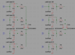
Something like this


It must detect - change polarity, low supply voltage, lost connection on lines.
 

Attachments

  • POE_Test.png
    POE_Test.png
    24.4 KB · Views: 885
Last edited:
Thanks for the schematic, thats exactly like what I was thinking,

This will then allow for quick and easy diagnosis to which wiring is in place and also if power is going through.

Do you have any more information on this circuit, as you have put about detecting low supply voltage, lost connection etc. What are the signs of each.

Thanks
 

If supply voltage less then 2*1.4+43~46V zener diodes D17-D120 will be closed, LEDs no light.
If one of lines lost connection LEDs attached to this line will no light.
If polarity on lines 4 and 8 is normal, will light D1 (green) and D8 (red), if the opposite will light D2(red), and D7(green).
 

hi,
I'm not sure your tester will work as a poe switch is intelligent
it only send the 48v supply if the poe device replies a certain sequence. the 48v are not always present on the wires.
 
  • Like
Reactions: pplus

    pplus

    Points: 2
    Helpful Answer Positive Rating
hi,
I'm not sure your tester will work as a poe switch is intelligent
it only send the 48v supply if the poe device replies a certain sequence. the 48v are not always present on the wires.
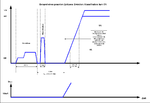
Yes, my fault. But in IEEE 802.3af PSE is very simple mechanism of classification.
To determine whether a PD is connected, the following input parameters are checked:
• characteristic resistance = RGOOD (19k − 26, 5k),
• typical resistance value = RTY P (25k),
• characteristic capacitance = CGOOD (max.150nF).
This method is called "Resistive Power Discovery".
PSEclass.png
PD rejection criteria
• resistance less than or equal RBADmin (<= 15k) or
• resistance greater than or equal RBADmax (>= 33k) or
• capacitance greater than or equal CBADmin (>= 10μF)
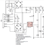
Hence it is necessary to connect the parallel resistor value 2 * RGOOD to inputs 4-7,5-8,1-3, 2-6, or use LTC4257
LTC4257.png
 
Status
Not open for further replies.

Similar threads

Part and Inventory Search

Welcome to EDABoard.com

Sponsor

Back
Top