Continue to Site

Welcome to EDAboard.com

Welcome to our site! EDAboard.com is an international Electronics Discussion Forum focused on EDA software, circuits, schematics, books, theory, papers, asic, pld, 8051, DSP, Network, RF, Analog Design, PCB, Service Manuals... and a whole lot more! To participate you need to register. Registration is free. Click here to register now.

[SOLVED] PNP Transistor Circuit - Switch or Amplifier?

Status
Not open for further replies.

sunny1

Newbie level 3
Joined
Feb 17, 2013
Messages
4
Helped
0
Reputation
0
Reaction score
0
Trophy points
1,281
Activity points
1,304
I am unable to figure out here if the the PNP transistor in this circuit acts as switch or amplifier? Can anyone please help me figure out how the output voltage Vout looks like in this circuit? Thanks! (Please see the attached image)
 

Attachments

  • PNP_Transistor.jpg
    PNP_Transistor.jpg
    2 MB · Views: 105

here you will get a voltage less than 10v and current with maxim rating of you transistor used
certainly this will not act as a switch its transistor feedback biasing circuit
better use resistor in feed back that will decide your o/p voltage
 
  • Like
Reactions: sunny1

    sunny1

    Points: 2
    Helpful Answer Positive Rating
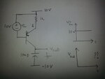
Vout should settle close to zero
 
  • Like
Reactions: sunny1

    sunny1

    Points: 2
    Helpful Answer Positive Rating
Simplify the circuit by replacing the b-e junction with a diode. What is the voltage at the cathode (base)? It is 10V - 10V = 0V. So what is the voltage at the anode (emitter)? It will be a diode drop higher at about 0.6V. When the transistor turns on it in effect connect the emitter and collector internally and thus the 0.6V will appear on the collector. So Vout will start charging from -10V to (0V + 0.6V) with an initial current of 9.4mA (10-0.6V)/1k, that tapers off according to the RC time constant.

Thank You very much!! It is very helpful!!
 

A transistor with a constant B-E voltage acts as a constant current source.
Charging a capacitor with a constant current source gives a linear voltage ramp across it. (assuming it was discharged at the start!).

Brian.
 

A transistor with a constant B-E voltage acts as a constant current source.
Charging a capacitor with a constant current source gives a linear voltage ramp across it. (assuming it was discharged at the start!).

Brian.

Yes, I forgot to mention that I was referring to the simple diode explanation. With the transistor in place, the charging current will be constant at about 9.4mA up to the knee voltage where it would rapidly drop to zero.

Also come to think of it the initial charging current using the diode model will actually be about twice 9.4mA . For the transistor it is fixed at (10-Vbe)/1k
 
Last edited:

So Vout will start charging from -10V to (0V + 0.6V) with an initial current of 9.4mA (10-0.6V)/1k, that tapers off according to the RC time constant.

As mentioned here, the transistor is a source of current, meaning t=dUC/I
 

Thank you all for your help!!
 

Status
Not open for further replies.

Similar threads

Part and Inventory Search

Welcome to EDABoard.com

Sponsor

Back
Top