Welcome to our site! EDAboard.com is an international Electronics Discussion Forum focused on EDA software, circuits, schematics, books, theory, papers, asic, pld, 8051, DSP, Network, RF, Analog Design, PCB, Service Manuals... and a whole lot more! To participate you need to register. Registration is free. Click here to register now.
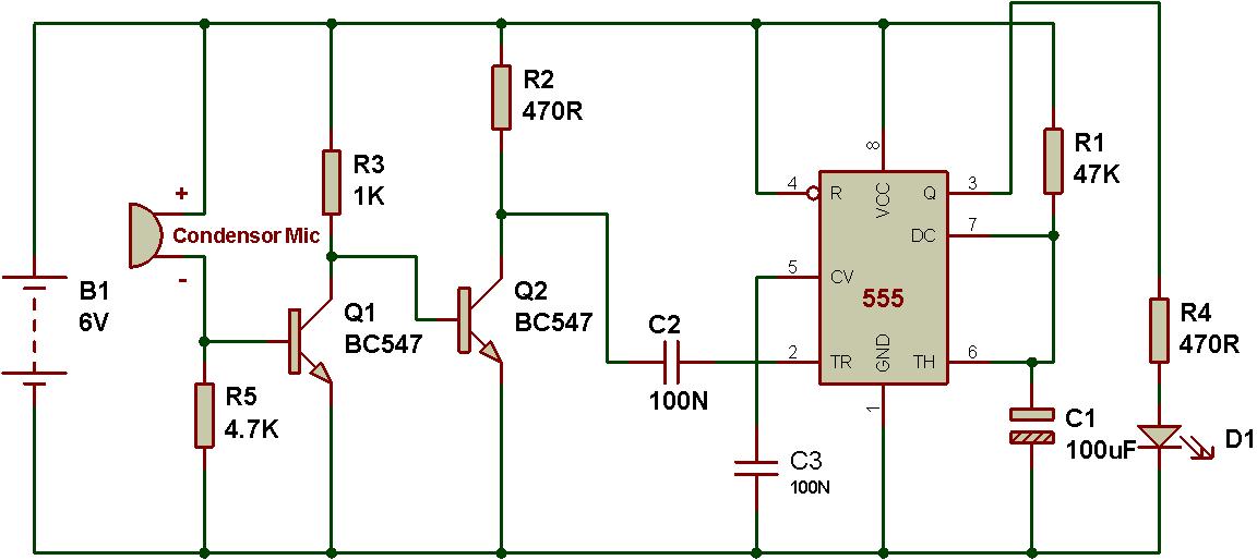
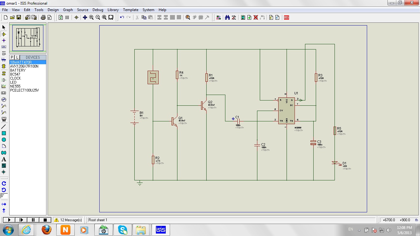
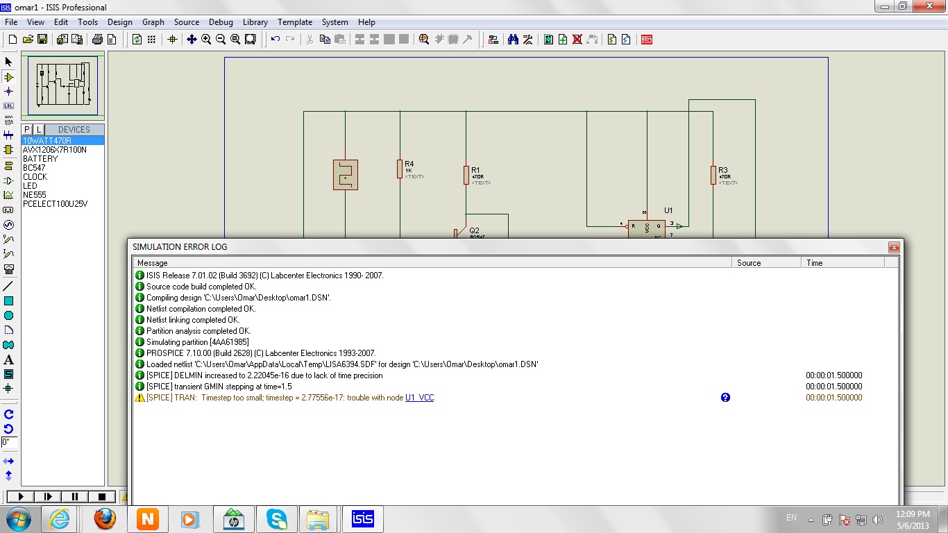
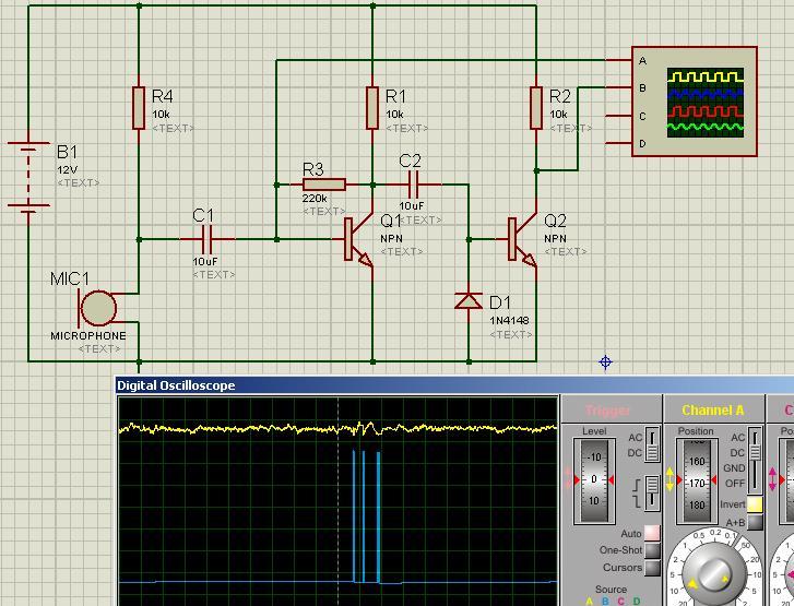
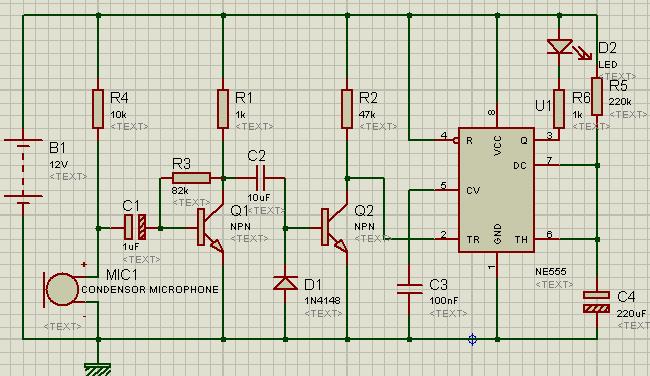
The circuit is not working on a breadboard so I tried to simulate it using proteus and unfortunately it didnt work...as it is shown in the screenshots.
I'm not really familiar with condensor mics, but something doesn't look right to me(actually, several things don't look right). Why is the mic connected between the base of Q1 and the positive supply? Wouldn't you want it connected between base and common? Your screen shots don't tell us what the simulation output looks like. For starters, What does the collector of Q1 look like with respect to the mic output? I don't think that the trigger input to the 555 is proper, either; I think you may need a pull-up there.
I'am very thankful ...but I'am a beginner and I need more help, can you give me a complete circuit ? or just edit my circuit , here is my circuit u can open in it in the simulator and edit what is wrong ...Thank you
one transistor is enough
without that also it'll work but sensitivity will be less.
10K pullup (biasing) resistor, cond mic, coupling capacitor is enough to trigger 555 IC.
One important fact about 555 is to pullup its pin#2 because it will only give ouput when pin#2 is driven low. Connect a 10k-100k resistor between pin#2 and +ve. Another point is about biasing the first transistor. Put an input capacitor between mic and base of first transistor and a biasing resistor at the base of the transistor. It is about the circuit you posted.
You can try with this circuit.
Note that output is activated for a predetermined time on sound detection. It is not bistable operation that is click on/ click off.
D1 helps to discharge input capacitor. It can be replaced with a resistor but with less sensitivity.As input is AC Negative going pulses conduct through this diode and negative voltage shorted to ground. Positive cycle pass through transistor BE junction
amplified in transistor and produce digital pulse at transistor collector.
This site uses cookies to help personalise content, tailor your experience and to keep you logged in if you register.
By continuing to use this site, you are consenting to our use of cookies.