Continue to Site

Welcome to EDAboard.com

Welcome to our site! EDAboard.com is an international Electronics Discussion Forum focused on EDA software, circuits, schematics, books, theory, papers, asic, pld, 8051, DSP, Network, RF, Analog Design, PCB, Service Manuals... and a whole lot more! To participate you need to register. Registration is free. Click here to register now.

[SOLVED] Plz Help ! ....I'am making a clap switch circuit ...Images attached

Status
Not open for further replies.

omarrr666

Newbie level 3
Joined
May 6, 2013
Messages
4
Helped
0
Reputation
0
Reaction score
0
Trophy points
1,281
Activity points
1,312


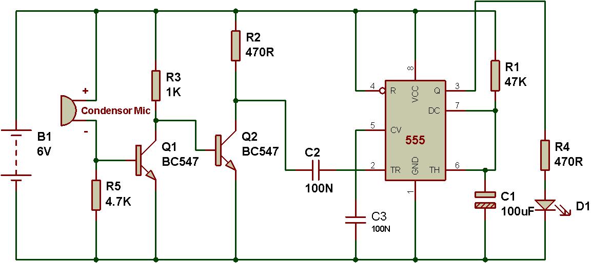
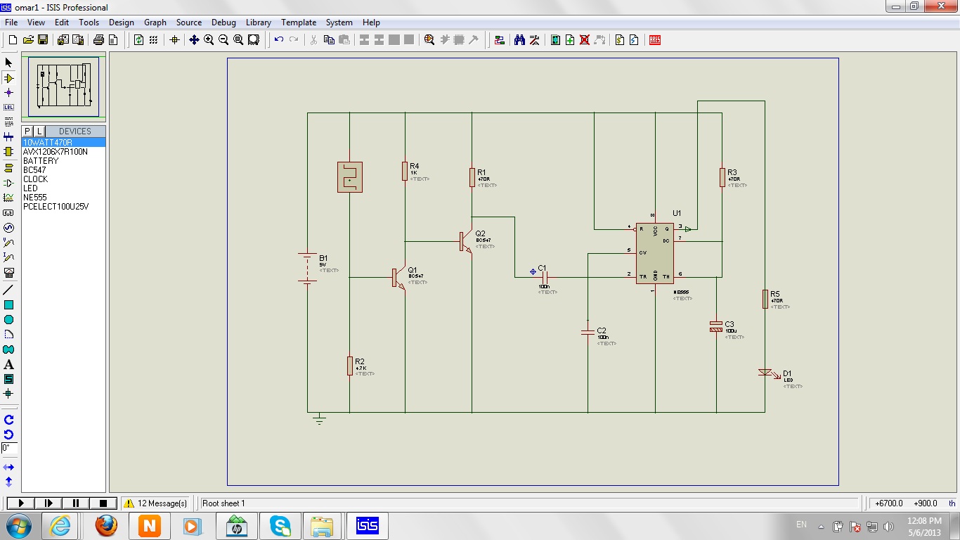
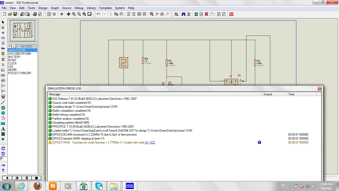
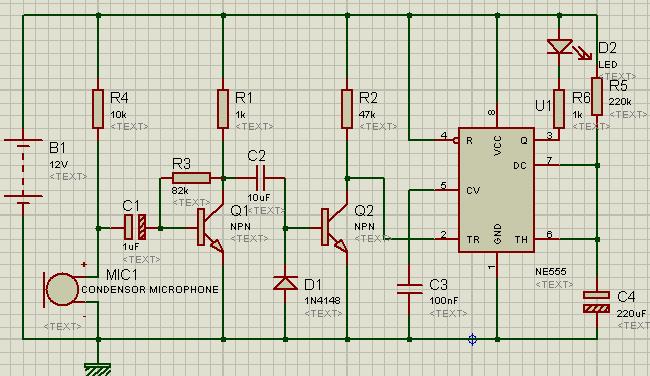
The circuit is not working on a breadboard so I tried to simulate it using proteus and unfortunately it didnt work...as it is shown in the screenshots.

Thanks in advance
 

I'm not really familiar with condensor mics, but something doesn't look right to me(actually, several things don't look right). Why is the mic connected between the base of Q1 and the positive supply? Wouldn't you want it connected between base and common? Your screen shots don't tell us what the simulation output looks like. For starters, What does the collector of Q1 look like with respect to the mic output? I don't think that the trigger input to the 555 is proper, either; I think you may need a pull-up there.
 

When sound is catched by microphone, the following circuit should generate negative going pulse to trigger the timer. Your circuit is not doing that.


Try this for input pulse shaping,
7028345300_1367849176.jpg


Practically connect mic to input and ground.

- - - Updated - - -

1421534900_1367850981.jpg
 

I'am very thankful ...but I'am a beginner and I need more help, can you give me a complete circuit ? or just edit my circuit , here is my circuit u can open in it in the simulator and edit what is wrong :) ...Thank you
 

Attachments

  • Simulation.rar
    12.5 KB · Views: 172

**broken link removed**

**broken link removed**

http://1.bp.blogspot.com/-_3ZG2NMrV...SBDLFdE/s1600/Clap_Sensitive_on-off_Relay.GIF

**broken link removed**

basic clap ckt without any IC only with transistor:
http://circuiteasy.com/clap-switch/
**broken link removed**


Front end:
http://embedded-lab.com/blog/wp-content/uploads/2012/11/ClapSensorCircuit.png
ref: http://embedded-lab.com/blog/?p=6439

- - - Updated - - -

one transistor is enough
without that also it'll work but sensitivity will be less.
10K pullup (biasing) resistor, cond mic, coupling capacitor is enough to trigger 555 IC.

555 clap.JPG
 

One important fact about 555 is to pullup its pin#2 because it will only give ouput when pin#2 is driven low. Connect a 10k-100k resistor between pin#2 and +ve. Another point is about biasing the first transistor. Put an input capacitor between mic and base of first transistor and a biasing resistor at the base of the transistor. It is about the circuit you posted.
You can try with this circuit.

9796652000_1368004744.jpg


Note that output is activated for a predetermined time on sound detection. It is not bistable operation that is click on/ click off.
 

Hi elecbaba,

can u pls explain what is the function of D1 diode in ur ckt.
 

D1 helps to discharge input capacitor. It can be replaced with a resistor but with less sensitivity.As input is AC Negative going pulses conduct through this diode and negative voltage shorted to ground. Positive cycle pass through transistor BE junction
amplified in transistor and produce digital pulse at transistor collector.
4025302500_1368023142.gif

6415659700_1368023289.gif

See these and other relevarnt circuits with explanation on this page,
http://www.talkingelectronics.com/projects/TheTransistorAmplifier/TheTransistorAmplifier-P2.html
 

thanks for ur explanation Mr. elecbaba
 

Thank you elecbaba :D , and thanks for everyone
 

Status
Not open for further replies.

Similar threads

Part and Inventory Search

Welcome to EDABoard.com

Sponsor

Back
Top