des_mozges
Newbie level 1
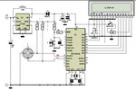
Hi everyone. I'm doing this hobby PIC project, basically it's a thermometer with LCD. I found both a schematics and code (hex file) in some well-known electronics related magazine and i decided to give it a shot. I should add I've never had any experience with uc, especially not PICs. The project didn't seem too difficult and it consists of only 3 IC (a pic, a sensor and DC-DC voltage regulator) , LCD display and a few other usual components. The schematic is attached below.
So i bought all the electronic components, PIC 16f786a and PIC Kit 3 (for programming my PIC). What i've done so far: I programmed my PIC (downloaded the 'hex' file and wrote it into the chip with pickit3) and set the project on a breadboard (protoboard) so that i could test it first. The problem is that it doesn't work. The LCD display doesn't seem to be turned on at all. Now, if i assume that all components are connected correctly (on the breadboard), then I guess the problem might only be in one (or more) of those three parts: PIC (and the code), LCD or the sensor. Like i said, i didn't write the code, but i believe it's written correctly (as i got it from the original author of that project (it was written in MikroBasic)). So checking the code would be the last thing for me to do. I want to check "hardware" parts first. So i decided to test those parts of the circuit, starting with LCD display.
My questions are:
1.) LCD: Any idea where to get a code or hex file for testing my LCD? I basically just want to see if it's working and i need some easy and quick test. Like "hello world" written on display or something. My LCD is 20 x 4 using standard 4-bit interface interface (HD44780 or KS066). Power supply (Vdd) is 5V.
2.) PIC & sensor: The temperature sensor I'm using is a very good one. It has internal ADC, RAM, DSP and it can work in two possible modes. The output temperature is already in digital form (15 bit word). Communicating between PIC and my sensor is via SMBus (very similar to I2C). As you can see on the schematic, the temperature sensor is connected to PIC via 2 pins: SCL (RC3) and SDA (RC4). If i understand correctly, PIC is Master (who provides clock signal) and the sensor is Slave. I checked SCL pin, which is supposed to be 'clock', but on oscilloscope it DOESN'T look like it at all. It's rather a DC signal (around 4,5V; power supply for the sensor, PIC and LCD is 5V) with some noise. So this is surely one of the problems. Any ideas what should I do next?
Any other advices or help would really be appreciated!