Continue to Site

Welcome to EDAboard.com

Welcome to our site! EDAboard.com is an international Electronics Discussion Forum focused on EDA software, circuits, schematics, books, theory, papers, asic, pld, 8051, DSP, Network, RF, Analog Design, PCB, Service Manuals... and a whole lot more! To participate you need to register. Registration is free. Click here to register now.

Please help asap in SPWM Inverter 24V to 220V 400Hz

Status
Not open for further replies.
Hi.

You want us to help. For this you need to provide information.

Did you read post#8? Show us the according scope pictures.

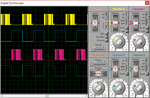
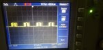
You tell it is 16kHz PWM. Maybe I'm wrong but I still see 400kHz. Please tell me how I can verify it is 16kHz.

Klaus
Hi, If you wants to see wave using scope, I can show you. I don't have pcb with me today. I can show you tomorrow.
For 16kHz, I am using PIC controller to generate SPWM of 400Hz with switching frequency 16kHz. I used https://tahmidmc.blogspot.com/2012/10/generation-of-sine-wave-using-spwm-in_10.html blog to get the required wave.

Code:
#include <xc.h>
#define _XTAL_FREQ 20000000

unsigned char sin_table[25]={0,2,4,7,9,11,12,14,15,16,17,18,18,18,18,17,16,15,14,12,11,9,7,4,2};


unsigned int TBL_POINTER_NEW, TBL_POINTER_OLD, TBL_POINTER_SHIFT, SET_FREQ;
unsigned int TBL_temp;
unsigned char DUTY_CYCLE;

void interrupt tc_int (void){
     if (PIR1bits.TMR2IF == 1){
        TBL_POINTER_NEW = TBL_POINTER_OLD + SET_FREQ;
        if (TBL_POINTER_NEW < TBL_POINTER_OLD){
           CCP1CONbits.P1M1 = ~CCP1CONbits.P1M1; //Reverse direction of full-bridge
        }
        TBL_POINTER_SHIFT = TBL_POINTER_NEW >> 12;
        DUTY_CYCLE = TBL_POINTER_SHIFT;
        CCPR1L = sin_table[DUTY_CYCLE];
        TBL_POINTER_OLD = TBL_POINTER_NEW;
        PIR1bits.TMR2IF = 0;
     }
}


void main() {
     SET_FREQ = 205;
     TBL_POINTER_SHIFT = 0;
     TBL_POINTER_NEW = 0;
     TBL_POINTER_OLD = 0;
     DUTY_CYCLE = 0;
     ANSEL = 0; //Disable ADC
     CMCON0 = 7; //Disable Comparator
     PR2 = 24;
     TRISC = 0x3F;
     CCP1CON = 0x4C;
     PIR1bits.TMR2IF = 0;
     T2CON = 4; //TMR2 on, prescaler and postscaler 1:1
     while (PIR1bits.TMR2IF == 0);
     PIR1bits.TMR2IF = 0;
     TRISC = 0;
     PIE1bits.TMR2IE = 1;
     INTCONbits.GIE = 1;
     INTCONbits.PEIE = 1;

     while(1);
}

This is the code I have used
 
Last edited by a moderator:

Hi,

I don´t think PR2 = 24 is correct. It´s too far from Tahmid`s "249"

Klaus

added...
Scope use:
Please don´t use "fine tune" on timing or vertical setup, unless you really need it. It just causes confusion. Set it to the default value.
Using those "0.94us/div" of post #13 then you get 200kHz which meets with the wrong "PR2=24".

FvM is experienced, thus he asked two days ago to show IR2110 input and ouput signals....

It may not solve all problems, but at least one....
 
Last edited:

Hello everyone. Unfortunately I was unable to post any scope wave because pcb was not with me yesterday. Today I post it. I think you all have asked for wave was nice suggestion for me. I found something different in the wave. As I generated a 400Hz using 20MHz crystal for PIC16F684 controller. I found that SPWM somehow fluctuating, like about +30% of 400Hz and -30% of 400Hz. Guide me if I am wrong. Here is the attached video for the SPWM https://drive.google.com/file/d/1II03v9myc_QqNK7HHnjg4B9Xz_mdxi2H/view?usp=drivesdk Please have a look on frequency variation.
Also, the calculation I did as:
(according to blog: https://www.engineersgarage.com/pic...sing-pwm-with-pic-microcontroller-part-19-25/)
Crystal: 20MHz
Tosc: 0.05us
Clock: 0.2us
Prescale: 1
Total Sampling Time: 0.2us*255 = 51us ~~ 50us (255 is correct value for sampling rate?)
One sine wave = 50us*50 = 2.5ms (50 steps for sine wave generation, I took 50 because it helps me to get 400Hz in calculation)
Frequency of one sine wave: 1/2.5m = 400Hz
(according to https://tahmidmc.blogspot.com/2012/10/generation-of-sine-wave-using-spwm-in_10.html blog)
Now, if PR2 = 24
PWM Period: (24+1)*4*0.05 = 5us (where 0.05us is tosc)
For half cycle: 5us*25 = 0.125
Half cycle of sine wave is : 2.5m/2 = 1.25
So, 1.25/0.125 = 10 (10 pulse needed) (according to tahmid blog)
2^11 = 2048
so, 2048/10 = 205
Hence set_freq is 205 in code

I want to know where I am wrong in generating 400Hz
--- Updated ---

Looking forward for your kind response as soon as possible.
--- Updated ---

Also, as Post #13 said by Klaus, my frequency is 400kHz on oscilloscope. I double check with the code provided in Tahmid blog which is: https://tahmidmc.blogspot.com/2012/10/generation-of-sine-wave-using-spwm-in_10.html
I got below mentioned signal with 16MHz as per the blog. Which is 2.13m in 5 or 4.75 division. which is equal to 93.896HZ What does it mean? Either my code is wrong or the way I am calculating (1/(2.13m*5)) = 93Hz where, acording to tahmid blog, they are generating 50Hz Guide me if I am wrong. My code is:
Code:
#include <xc.h>
#define _XTAL_FREQ 16000000

unsigned char sin_table[32]={0,25,49,73,96,118,137,
159,177,193,208,220,231,239,245,249,250,249,245,
239,231,220,208,193,177,159,137,118,96,73,49,25};


unsigned int TBL_POINTER_NEW, TBL_POINTER_OLD, TBL_POINTER_SHIFT, SET_FREQ;
unsigned int TBL_temp;
unsigned char DUTY_CYCLE;

void interrupt tc_int (void){
     if (PIR1bits.TMR2IF == 1){
        TBL_POINTER_NEW = TBL_POINTER_OLD + SET_FREQ;
        if (TBL_POINTER_NEW < TBL_POINTER_OLD){
           CCP1CONbits.P1M1 = ~CCP1CONbits.P1M1; //Reverse direction of full-bridge
        }
        TBL_POINTER_SHIFT = TBL_POINTER_NEW >> 11;
        DUTY_CYCLE = TBL_POINTER_SHIFT;
        CCPR1L = sin_table[DUTY_CYCLE];
        TBL_POINTER_OLD = TBL_POINTER_NEW;
        PIR1bits.TMR2IF = 0;
     }
}


void main() {
     SET_FREQ = 410;
     TBL_POINTER_SHIFT = 0;
     TBL_POINTER_NEW = 0;
     TBL_POINTER_OLD = 0;
     DUTY_CYCLE = 0;
     ANSEL = 0; //Disable ADC
     CMCON0 = 7; //Disable Comparator
     PR2 = 249;
     TRISC = 0x3F;
     CCP1CON = 0x4C;
     PIR1bits.TMR2IF = 0;
     T2CON = 4; //TMR2 on, prescaler and postscaler 1:1
     while (PIR1bits.TMR2IF == 0);
     PIR1bits.TMR2IF = 0;
     TRISC = 0;
     PIE1bits.TMR2IE = 1;
     INTCONbits.GIE = 1;
     INTCONbits.PEIE = 1;

     while(1);
}
1597162597546.png
 
Last edited:

Hi
Hi, If you wants to see wave using scope, I can show you
Why not use the simulator's scope?

Again: please set the fine-tune of the timing to the default value.
I see no improvement in "2.13ms/div" --> use "2ms/div".
It already confused you, it already confused me --> avoid even more confusion.

And again: set correct trigger source to get a stable scope view. Use "B" or "D" with a threshold of about 2V.

Then correct your software to get the desired signals. In my eyes it makes no sense to debug a circuit with signals.
First things first.
Currently I see a period time if about 9.6 x 2.13ms = 19.8ms. (Maybe 20ms = 50 Hz)
But you want 400Hz, don't you?

Next step is to zoom into PWM and rectify the software to get the desired PWM frequency.

Next step is to show us the input and output signals of one IR2110 in one scope picture. (Only one half bridge).

Klaus


Hello, I redesign the code to get 400Hz SPWM (but still I am unsure because of variation in the result)
Please find the below attached file of Proteus and Oscilloscope simulation. In proteus I am getting 400Hz and in scope I am getting 4kHz. Why?
Here is the code I made using 20Mhz crystal for 20kHz switching frequency :
Code:
#include <xc.h>
#define _XTAL_FREQ 20000000

unsigned char sin_table[25]={0, 31, 62, 92, 120, 147, 171, 193, 211, 226, 238, 246, 250, 250, 246, 238, 226, 211, 193, 171, 147, 120, 92, 62, 31};


unsigned int TBL_POINTER_NEW, TBL_POINTER_OLD, TBL_POINTER_SHIFT, SET_FREQ;
unsigned int TBL_temp;
unsigned char DUTY_CYCLE;

void interrupt tc_int (void){
     if (PIR1bits.TMR2IF == 1){
        TBL_POINTER_NEW = TBL_POINTER_OLD + SET_FREQ;
        if (TBL_POINTER_NEW < TBL_POINTER_OLD){
           CCP1CONbits.P1M1 = ~CCP1CONbits.P1M1; //Reverse direction of full-bridge
        }
        TBL_POINTER_SHIFT = TBL_POINTER_NEW >> 11;
        DUTY_CYCLE = TBL_POINTER_SHIFT;
        CCPR1L = sin_table[DUTY_CYCLE];
        TBL_POINTER_OLD = TBL_POINTER_NEW;
        PIR1bits.TMR2IF = 0;
     }
}


void main() {
     SET_FREQ = 2621.44;
     TBL_POINTER_SHIFT = 0;
     TBL_POINTER_NEW = 0;
     TBL_POINTER_OLD = 0;
     DUTY_CYCLE = 0;
     ANSEL = 0; //Disable ADC
     CMCON0 = 7; //Disable Comparator
     PR2 = 249;
     TRISC = 0x3F;
     CCP1CON = 0x4C;
     PIR1bits.TMR2IF = 0;
     T2CON = 4; //TMR2 on, prescaler and postscaler 1:1
     while (PIR1bits.TMR2IF == 0);
     PIR1bits.TMR2IF = 0;
     TRISC = 0;
     PIE1bits.TMR2IE = 1;
     INTCONbits.GIE = 1;
     INTCONbits.PEIE = 1;

     while(1);
}
 

Attachments

  • Proteus_400Hz.png
    Proteus_400Hz.png
    82.5 KB · Views: 70
  • Scope_Hz.jpg
    Scope_Hz.jpg
    53.9 KB · Views: 63

Status
Not open for further replies.

Part and Inventory Search

Welcome to EDABoard.com

Sponsor

Back
Top