Continue to Site

Welcome to EDAboard.com

Welcome to our site! EDAboard.com is an international Electronics Discussion Forum focused on EDA software, circuits, schematics, books, theory, papers, asic, pld, 8051, DSP, Network, RF, Analog Design, PCB, Service Manuals... and a whole lot more! To participate you need to register. Registration is free. Click here to register now.

PIONEER DV696 AVS power supply failure

Status
Not open for further replies.

zepus169

Newbie level 5
Joined
Apr 19, 2020
Messages
10
Helped
1
Reputation
2
Reaction score
1
Trophy points
3
Location
BUCHAREST, RO
Activity points
113
Hi, everyone!
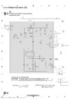
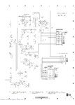
I've been using for many years a very nice SACD player PIONEER DV 696AVS. Fully satisfied by the quality. Few months ago comes to develop a very nasty problem: after powering on, few seconds is showing ON, then is switching OFF and is taking a very long time until possible to switch ON again. Or happens during playing back of second or third audio track. Suspecting some capacitor to be old and exhausted, I did found and downloaded the electronic diagram from net and dismounted the unit, started to search for the "overgrown" electrolytic capacitors in the power supply board A2J003A240. First impression was that C511 / 82microF / 400V been out of order, found a similar and replaced, even the old one seemed to be ok. Voltage before the trafo is around 82V, in schematic says some 130V. Ok, for 2-3 days was working, then resumed to stop immediately after start, just like before. Definitely something in the power board. All diodes in the rectifier bridge are good. Can somebody give me a hint about where can be the problem, or I better start searching for another unit which is still working?
Thanks a lot.
 

Hi, again!
Trying to upload some picture with schematic.
 

Attachments

  • Pioneer dv696avs - power unit_Page_1.jpg
    Pioneer dv696avs - power unit_Page_1.jpg
    220.2 KB · Views: 150
  • Pioneer dv696avs - power unit_Page_2.jpg
    Pioneer dv696avs - power unit_Page_2.jpg
    278.1 KB · Views: 124

My guess would be the capacitor (C500? - it's difficult to read) directly above the word "Against" in the warning box on the second schematic. My next best guess would be IC504.

Brian.
 

taking a very long time until possible to switch ON again. Or happens during playing back of second or third audio track.

Maybe slow heat buildup? Since there are times the unit operates for a few minutes.

A thermal camera is just the right diagnostic tool (but expensive).

Freeze spray is often used as well.

Or touch components to locate the hot one.
 

if you can get a Dong Guan xintai thermal cam (HT-04) then this is good value for money.....not great resolution, but has max temp hold which means you dont have to hold your hand still to hold on the hottest thing in the window.

- - - Updated - - -

If you can look at the temp of the smps control chip that would be good

Also, are your output voltages correct...if one secondary is overloaded than the supply (smps control chip)may eventaully go into overtemperature shutdown.

- - - Updated - - -

Can you run it with enclosure off, then aim a fan over the control chip and see if it does NOT then shut down...ie youre cooling it so it doesnt go into overtemp trip.

- - - Updated - - -

What voltage is 82v did you say?....Primary HV bus should peak at around 330V or so.
What mains are you running this on?...its meant for 230vac.
it could overheat if run on 120vac

- - - Updated - - -

The RCD clamp resistor seems a rather high resistance.
What is your peak drain voltage when on max load/max vin?

- - - Updated - - -

Try to also replace the Vcc rail capacitor of the smps controller IC

- - - Updated - - -

Have you got an AC power meter...can you run it and see what rela power its drawing.....AC plug meters are cheap.....is it overloaded?
 

Hello, people!
Glad to see that replies comes and even very fast. First of all, I am fond of this unit, even though I am using now a replacement (DANON 1930), sound is slightly different and I missing it. Not complaining, not making any compare, just my humble impression.
Regarding the components, I have been under the impression that I should exchange all electrolytic capacitors in the power supply board, first of all. Then, if nothing change, to try for a replacement of C506 and C509, than maybe for opto-coupler IC504.

I will try to reply / update with more info.
Did not feel like some extra heating on elements. Did not have a thermal camera, but an IR temperature sensor which I am checking all sensible elements (IC's, capacitors, trafo, transistors and resistors). No high deviation between that to be critical (few Celsius degrees).
About testing without cover, sure, otherwise I cannot measure some voltages around terminals and check temperature. Nothing change, though. Not yet tried to put a fan for cooling, I will try tomorrow.
The voltage I am talking is measured between GND and different terminal, as shown in the diagram, with a FLUKE 87V, which served me well for more than 15 years.
At this moment, due to limiting of movement because of restriction with COVID-19, I cannot access my other instruments from the summer house, where I keep them and some electronic spares. But tomorrow I will make some more measurements and will post here.
Thanks again
 

Hi, again!
I did some more checking on the unit. This time, even it was long time not tested, it did not start even once on my tests. Supply voltage is 230Vac, european type (50Hz). Voltage on outlet of rectifier bridge is 331Vdc, more or less stable (sometimes shown 229, sometimes 331, I guess proportional with input voltage).
Voltage on pin 2 (VCC) of IC502 jumps from 12 to 15Vdc almost once/second, normally during POWER ON should be around 17,5Vdc., means is self-blocking. Voltage on pin 4 (FB/OLP) is 0 to 0,4Vdc, whilst in diagram is shown 3,9Vdc. I have removed and checked all components in the control / feed-back and supply of IC 502 and seems ok. Now I am seriously concern about the opto-coupler IC 504, his circuit of control or the POWER CONTROL IC502.
If I will disconnect R507 (10 OHMS / 0,25W connection between opto-coupler outlet and IC 502 pin 4), is something wrong can happen to the IC502 (like overvoltage / overheat - burning out)?
I would like to know what is the normal voltage on pin 4 of IC 502 (SANKEN A6151) during normal operation.
I also think that is possible to be something in the circuit of activating opto-coupler. At this moment, I did tested only the main switch contacts and looks ok.
 

it was long time not tested, it did not start even once on my tests.

Previously after turning on the unit it worked briefly. Lack of response now suggests that an idle period allowed circuits to fall to zero (which can happen as capacitors drain).

Voltage on pin 2 (VCC) of IC502 jumps from 12 to 15Vdc almost once/second

Does this happen repeatedly? It sounds as though it's a test procedure. Except that something is wrong, therefore it repeats again and again?

Your problem may be in a component that is either:

(a) abnormally high resistance in the current path sending power to the supply rails. (Such a component would not necessarily overheat.)

or

(b) abnormally low resistance draining current from the supply rails, severely dropping volt levels. (This would raise a device temperature.)

Or multiple problems in multiple components.

Something to try: Use your external power supply to apply higher voltages at test points where you measure low voltage. Notice whether it draws overmuch current from your supply. It's reckless but it may raise volt levels to a point where the unit turns on at least for a minute.

Also since you mention the optocoupler led...
Try to get an idea of the current level through it. It looks easy to measure voltage across resistor 514, then divide that by its ohm value (1k). Factor in R515 (1k). This could diagnose whether the led deteriorated over the years.
 

Voltage on pin 2 (VCC) of IC502 jumps from 12 to 15Vdc almost once/second
Does this happen repeatedly? It sounds as though it's a test procedure. Except that something is wrong, therefore it repeats again and again?
More likely it is in hiccup mode, trying to start, failing and retrying again.
This doesn't sound like a thermal problem to me, either something is overloading the output and causing it to shut down or more likely it isn't able to produce enough output power, tries to ramp up the output and then gives up. I would certainly target the capacitors first.

Brian.
 

This doesn't sound like a thermal problem to me, either something is overloading the output and causing it to shut down or more likely it isn't able to produce enough output power, tries to ramp up the output and then gives up. I would certainly target the capacitors first.
This also sounds liek it to me....you are reporting HV DC Bus going from 229 to 339 so something is loading that down...as you have a biy 'lytic cap on that rail.

Maybe you shoudl one by one disconnect secondaries and see where the overloading stops
 

Hi, everyone!
First of all, my big mistake was about DC HV - instead of 229V I wanna say 329V, so "hunting" of HV is only 2, maximum 3 volts.
During my last testing today, did not know how, but unit started for a few minutes, time when I could do few more measuring:
IC502 pin 2 (VCC) = 18,2V ; pin 4 (FB/OLP) = 1,4V same like output of opto-coupler.
In few minutes, OFF again. Been testing the ON/OFF switch and remote control, no improvement. Also, removed R507, no change.
I have an ideea for tomorrow: disconnect R507 and apply 1er,5V dc from a battery to pin 4 of IC 502, maybe it will be forced to wake and sustain the power. Worst case? Burn everything down and I can sleep peacefully.
Thanks again for your insights.
 

During my last testing today, did not know how, but unit started for a few minutes

A lucky break. Does this mean you could hear audio?

If so then it gives you a valuable diagnostic tool.

* Did both left & right channel produce sound?

* Was hum present in either L or R channel? Clicks or buzzing or popping?

* Did L or R channel fade or act different from the other channel?

If so then it suggests the problem is not the power supply but in one channel's circuitry, causing shut-off.

However if both channels match in all ways, then it implies the power supply really is at fault.
 

Hello, again!
As promised, last update. Tested with a external voltage 1,5 V dc on pin 4 of IC 502 and I get output voltages from Power Supply Unit. Player started, but only for few seconds. Most probably opto-coupler is weak. After I'll get the chance to get my spares and workbench, I will replace and keep posted.
Thanks
 

Hello, again!
Since I get one request about last development, I can only say that I get the spare IC 502 and 504, and replaced, but still no success. Presently I am busy with my job, but I will post if I will manage to fix it.
 

solder joints don't last forever - get a hot iron and a good flux cored solder ad resolder everything you can get to ...
 

Status
Not open for further replies.

Similar threads

Part and Inventory Search

Welcome to EDABoard.com

Sponsor

Back
Top