kanni1303
Full Member level 3

- Joined
- Jun 29, 2012
- Messages
- 164
- Helped
- 12
- Reputation
- 24
- Reaction score
- 11
- Trophy points
- 1,298
- Location
- Chennai, Tamil Nadu, India
- Activity points
- 2,719
I am planned to build a project from the following link:
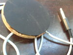
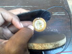
https://edrum.info fromt his link I made my PCB circuit.. with a slight changes I made the circuit to work fine with naked crytal(without any cover or others).. and I made a cover to my piezo crystal as attcahed in the photo, this was with a wooden piece cutted into round and piezo covered with a rubber(since I am going to hit the crystal with hand I chosed rubber that will make less pain to my fingers) but now the problem was I am not able to get signals from the crystal what I made with even a gain of 11 I fixed for the amplifier...
I can't suspect the crystal since the same setup was working fine with SPD-20 module( I bought from Roland) with my fingers...
I am not able to get any signal fromt the amplifier when I use it in my EDRUM project but the same crystal setup working fine with Roland SPD-20 module... what i lack from Roland module... should I increase the gain higher than this or something else I should make... I can't change the setup of crystal because it fits perfectly for my project and since it is working with accurate sensitive with Roland SPD-20 module...
Kindly poitn me where was the problem... All suggestions are welcomed in any degree...