mvs sarma
Advanced Member level 3
- Joined
- Apr 23, 2006
- Messages
- 786
- Helped
- 122
- Reputation
- 246
- Reaction score
- 80
- Trophy points
- 1,308
- Location
- Hyderabad, India.
- Activity points
- 5,579
perhaps after bypassing the VDD tgt adjme_guitarist said:any news on this project?
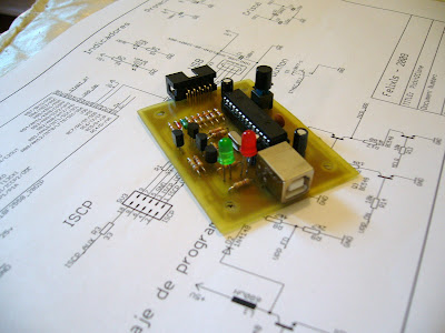
My board work very well since I built.