Continue to Site

Welcome to EDAboard.com

Welcome to our site! EDAboard.com is an international Electronics Discussion Forum focused on EDA software, circuits, schematics, books, theory, papers, asic, pld, 8051, DSP, Network, RF, Analog Design, PCB, Service Manuals... and a whole lot more! To participate you need to register. Registration is free. Click here to register now.

PicKit 2 FULL with TH components - Need help with layout

Status
Not open for further replies.
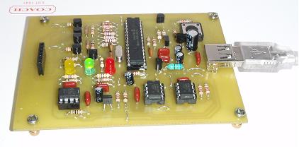
pickit2 vdd and vpp voltage level

mvs sarma said:
this line was again due to the schematic . please see that there is no Vusb connection shown over there.
I stead, have a double check of your schematic with microchip one and make independent artwork. you gain experience and that is what we are all around here on this wonderful site -- otherwise, the best would be like me to have a microchip pickit2 at 35/+ or BP10/+ as EPE reader and UK resident if the time did not expire yet.
sarma

I have double checked my schematic agaisnt the microchip one and it all checks out correct , If you look at the microchip on you will see that there is +5_usb connections every where, These al join up on the PCB. I have corrected the list you gave, I do not need to alter the connections on the USB socket has this is the same when I deisgned the GTB+P progrommer. Iknow where your comig from about how cheap they are to buy but that takes all the fun out of the hobby plus if you make your own then you can repair it if goes faulty where has the orginal one could be fiddley to repair been SMT :D

That's why I always draw the schematic fisrt and double check it then transfer to PCB this will reduce errors by loads, At least if the schematic is correct you know 100% your PCB will be 100%, I found in the past the time it take me to draw the PCB then made one then you found errors then in some case to correct it you have to redesign the PCB to cater for the errors, It only took me 1/2 hour to draw the pickit2 schematic so this way I know the PCB will be correct, So even if for hobby or a customer the schematic get drawn, Perhaps that's me been old school :D

nishal

look forward to teh nmew PCB, I only wanted the PCB file to compare against the schematic and i suppose been a little lazy andf not design my own :D
 

bs170 replacement 3904

Hello all,

Just want to clarify one thing:

But to my surprise, the placement some of them was correct! was it due to manual forced routing?
For the record, it was due to manual forced routing. That is why mine works with an apparently "incorrect" schematic/layout.

I hope that clears some confusion.

Computerman29
 

vpp before vdd

Computerman29 said:
Hello all,

Just want to clarify one thing:

But to my surprise, the placement some of them was correct! was it due to manual forced routing?
For the record, it was due to manual forced routing. That is why mine works with an apparently "incorrect" schematic/layout.

I hope that clears some confusion.

Computerman29
Thanks Computerman29 !!

Sarma
 

pickit2 eagle schematic

wizpic said:
mvs sarma said:
this line was again due to the schematic . please see that there is no Vusb connection shown over there.
I stead, have a double check of your schematic with microchip one and make independent artwork. you gain experience and that is what we are all around here on this wonderful site -- otherwise, the best would be like me to have a microchip pickit2 at 35/+ or BP10/+ as EPE reader and UK resident if the time did not expire yet.
sarma

I have double checked my schematic agaisnt the microchip one and it all checks out correct , If you look at the microchip on you will see that there is +5_usb connections every where, These al join up on the PCB. I have corrected the list you gave, I do not need to alter the connections on the USB socket has this is the same when I deisgned the GTB+P progrommer. Iknow where your comig from about how cheap they are to buy but that takes all the fun out of the hobby plus if you make your own then you can repair it if goes faulty where has the orginal one could be fiddley to repair been SMT :D

That's why I always draw the schematic fisrt and double check it then transfer to PCB this will reduce errors by loads, At least if the schematic is correct you know 100% your PCB will be 100%, I found in the past the time it take me to draw the PCB then made one then you found errors then in some case to correct it you have to redesign the PCB to cater for the errors, It only took me 1/2 hour to draw the pickit2 schematic so this way I know the PCB will be correct, So even if for hobby or a customer the schematic get drawn, Perhaps that's me been old school :D

nishal

look forward to teh nmew PCB, I only wanted the PCB file to compare against the schematic and i suppose been a little lazy andf not design my own :D

Wizpic, Its not your schematic we are talking about... Its all about CM29's schematic. Look at the attached pdf.

Even if I draw the CM29's schematic, I will make mistake since I copy the same error. :D I am bit backward to draw the schematics for myself since I give priority to my client pcbs.

Nishal
 

mcp6001 eagle

This is my version of Nisahl's PCB so far all components are placed just the routing now to take palce, I've only copied Nishahl's layout and altered some foot prints to siut mine, So the main credits go yo Nishal

I alaways do my PCB this way has you can see if there are any errors or components to close together and not only that you can visualy see what your PCB is going to look like

wizpic
 

is the atmel 24lc512 as 24c512

I am waiting your complete schematic Nishal. Please share it !
 

th components

samneang said:
I am waiting your complete schematic Nishal. Please share it !

Myself & Sarmaji is getting the same result "VDD/VPP Error" although all the components are placed correctly. We are analysing the problem... I will update the artwork as soon as we could solve the issue.

Nishal
 

pickit 2 in india

Hello All,

I had the same problem until I soldered a .1uF 0805 SMT ceramic cap on the bottom of the board between the power pins of the PIC, so make sure the PIC is properly bypassed.

Also,

Manually
Check, check, and check again the libraries of the MOSFET's to make sure the footprints are internally routed properly to the schematic. In the Eagle library I used, the drain and source were properly labeled, the footprint was correct, but the signals were mixed up. I did not discover the problem until I manually checked them. That's what caused all of this confusion in the first place.

BTW, excellent job on the board! It looks great! Much better than mine!!

Computerman29
 

pickit 2 vpp voltage level error. check target &

Computerman29 said:
Hello All,

I had the same problem until I soldered a .1uF 0805 SMT ceramic cap on the bottom of the board between the power pins of the PIC, so make sure the PIC is properly bypassed.

Also,

Manually
Check, check, and check again the libraries of the MOSFET's to make sure the footprints are internally routed properly to the schematic. In the Eagle library I used, the drain and source were properly labeled, the footprint was correct, but the signals were mixed up. I did not discover the problem until I manually checked them. That's what caused all of this confusion in the first place.

BTW, excellent job on the board! It looks great! Much better than mine!!

Computerman29
AS YOU can find, Nishal has incorporated a 0.1cap with a new name C16 .
as we are yet to get MCP6271, we are trying with alternate chips. Even though, CA3140 worked, it was slow raise of Vdd causing problem. we might take time to get MCP device.

Sarma
 

pickit 2 680uh

Samra.Nishal
Not sure if this may be causing your problem but I imported your PCB into Altium and when I placed all my compontnets and came to trace the route some of the transistor foot prints did not match the foot print that I have, I always thought the base of a transsitor went to the middle and not say pin3 ? if it is the 2N3906,2N3904 uou have used ?
 

pickit2 usb trouble

wizpic said:
Samra.Nishal
Not sure if this may be causing your problem but I imported your PCB into @ltium and when I placed all my compontnets and came to trace the route some of the transistor foot prints did not match the foot print that I have, I always thought the base of a transsitor went to the middle and not say pin3 ? if it is the 2N3906,2N3904 uou have used ?

Thanks for your thoughts.
coming to components, the CM29 schematic expects BC639 and BC640
these devices as supplied by Philips and others have a foot print of ECB. Due care is taken while mounting. I have enough experience of 40 years in Telecom related electronics servicing. Placement issue is well taken care.

we may not export artwork into another package directly, we need to modify the component definition like 2N3904(6) inplace of BC640(39) and then make revised layout. we may , as i was suggesting, even try for a fresh overlay of components. The PICKIT2 internal photos were once published in EPE magazine June 2007 issue. Obviously that would be best overlay even if through hole components are used.

Sarma
 

replacement for bs250

Hi guys,

I connected the board & I get a msg PICkits not found. Any possibility error on my board?

Added after 56 minutes:

how to check if my PIC18f2550 has burned?
 

irlml5103 pinout

me_guitarist said:
Hi guys,

I connected the board & I get a msg PICkits not found. Any possibility error on my board?

Added after 56 minutes:

how to check if my PIC18f2550 has burned?

To chk pic is burned
1. Winxp will detect the new device as pickit2 on the very first plug in
2. on subsequent plug in, if pickit2 is recognised under WinXP, the device manager will have a title "Human Interfaces devices"

Nishal
 

bs250 pnp

me_guitarist said:
Hi guys,

I connected the board & I get a msg PICkits not found. Any possibility error on my board?

Added after 56 minutes:

how to check if my PIC18f2550 has burned?

you have used another programmer to program the 18F2550
use the same, load the firmware into the programmer and verify whether the chip passes. also if there is a reversal of D+and D- wires , same thing would happen.
Take a DMM and check for power for all devices as per schematic.

Sarma
 

cadsoft eeprom 24c512

The Green LED lit up. I checked all components are all correct.

1. I use Atmel 24C512 instead of Microchip 24LC512, will this be any problem?

2. The P-channel Mosfet is Zetex BS250P.

3. N-Channel is BS170.

I'll check my PIC18F2550 using ICSP connection to make sure its ok.

At the 1st time I connect to PC the MCP6271 getting very hot so I disconnect it immediately, on that time the yellow LED does lit up, Winxp showing USB device not recognize.

25_1233326039.jpg


Diode on bottom side.
 

pickit2 mosfet

I programed the PIC18F2550 with original Microchip PICkit2 now windows recognized it. But facing the same problem that it can't be calibrate.

The voltage on the ICSP is only 0.157VDC & getting the MSG "PICkit2 VDD and VPP voltage level errors.Check target & retry operation".
 

pickit2 bc639

me_guitarist said:
I programed the PIC18F2550 with original Microchip PICkit2 now windows recognized it. But facing the same problem that it can't be calibrate.

The voltage on the ICSP is only 0.157VDC & getting the MSG "PICkit2 VDD and VPP voltage level errors.Check target & retry operation".

Is this message showing while mcp6271 in the board?

Nishal
 

atmel 24c512 pickit2

nishal said:
me_guitarist said:
I programed the PIC18F2550 with original Microchip PICkit2 now windows recognized it. But facing the same problem that it can't be calibrate.

The voltage on the ICSP is only 0.157VDC & getting the MSG "PICkit2 VDD and VPP voltage level errors.Check target & retry operation".

Is this message showing while mcp6271 in the board?

Nishal
Nice that you have ZETEX component that exactly suits your artwork for BS250

you may better upload the artwork you did along with component overlay. Because, In Nishal's Board the Transistors followed the order ECB while what you monted appears staaight with no swaps. Did you use Philps type BC6xx that follow ECB pinout? Or did you make changes in artwork?

Getting 0.157V is really damaging. With Nishal's Board , I have used all Tant capacitors. While I am yet to finalise, i get only Vdd voltage level error. this comes perhaps due to delay in getting Vpp and Vdd as we call the software. the delay can be attributed to heavy value and leaky electrolytic capacitors.

BTW, 0.157V is measured at what time? after the message. the page opens up. the Vdd would only come while you call for calibration, not until then. there it outputs 4.000 and expects you to really measure at ICSP and enter the value you got. There after follow the procedure as the page indicates.

Sarma
 

schema pickit complete vdd vpp

mvs sarma said:
Nice that you have ZETEX component that exactly suits your artwork for BS250

you may better upload the artwork you did along with component overlay. Because, In Nishal's Board the Transistors followed the order ECB while what you monted appears staaight with no swaps. Did you use Philps type BC6xx that follow ECB pinout? Or did you make changes in artwork?

Getting 0.157V is really damaging. With Nishal's Board , I have used all Tant capacitors. While I am yet to finalise, i get only Vdd voltage level error. this comes perhaps due to delay in getting Vpp and Vdd as we call the software. the delay can be attributed to heavy value and leaky electrolytic capacitors.

BTW, 0.157V is measured at what time? after the message. the page opens up. the Vdd would only come while you call for calibration, not until then. there it outputs 4.000 and expects you to really measure at ICSP and enter the value you got. There after follow the procedure as the page indicates.

Sarma

Dear Sarma,
What brand u r using for BC639 & BC640?
I don't know what brand of BC639 & BC640 am using as I bought from an electronic shop that doesn't much support technical data.

I'm using Nishal's layout & did not make any changes to the layout.

The BS170 is On-Semi, Epprom Atmel24C512,Op-Amp MCP6271.

I can't make sure do I get the correct 1N5818 & 1N5819 as the marking are blur & I bought from another small electronic shop that is not reliable & they have less knowledge on electronic components & maybe they give equivalent components.

I measured the voltage when I call for calibration, on the screen msg ask us to measure & enter the actual measured voltage. Its only 0.157VDC.

I used E-Cap for the 0.47uf cap do this make any problems?
 

Status
Not open for further replies.

Similar threads

Part and Inventory Search

Welcome to EDABoard.com

Sponsor

Back
Top