Vilius_Zalenas
Newbie level 4
Hi guys,
I have been learning to program mentioned PIC32 model for quite some time for a big project in the future. I came to I2C communication part which will be key feature in my project, I have not done anything with an I2C protocol in the past on any microcontroller ever, so I am a complete beginner with I2C. For now, my program goal is to write anything to 24LC512 eeprom chip via I2C bus (since I am working on a breadboard, the verification that eeprom was written successfully would be reading the eeprom with my TL866II+ memory programmer and seeing the data I wrote to eeprom via my pic32 code). After examining protocol`s architecture and hours of datasheet reading I came up with some I2C setup code (I know it may not be very efficient, but lets not take it so far right now). And that code seems partially correct. I looked at my SDA and SCL lines via logic analyzer and I saw some casual I2C data packet (using 100kbit/s so 50kHz frequency). However, when I hooked my 24LC512 to the TL866II+ and read it, the memory map was completely empty (TL866II+ is working properly, I verified it in the past). So where is the problem? My 24LC512 wiring:
Vdd is at +3.3V
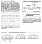
A2 A1 A0 all grounded
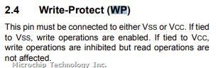
WP is directly connected to Vdd (to enable write operations to the chip)
SDA and SCL both pulled up via 5.1k ohm resistors
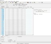
I am not sure is it even a software problem, but my wiring looks just like the 24LC512 datasheet recommendations, and I am getting an actual I2C data packet on my SDA line at 100 kbit/s or 50 kHz (as you like it). This looks quite scary to me, because I have no idea what to look for anymore. I really appreciate any help or hints for the beginner of fabulous I2C world.
Vilius
I have been learning to program mentioned PIC32 model for quite some time for a big project in the future. I came to I2C communication part which will be key feature in my project, I have not done anything with an I2C protocol in the past on any microcontroller ever, so I am a complete beginner with I2C. For now, my program goal is to write anything to 24LC512 eeprom chip via I2C bus (since I am working on a breadboard, the verification that eeprom was written successfully would be reading the eeprom with my TL866II+ memory programmer and seeing the data I wrote to eeprom via my pic32 code). After examining protocol`s architecture and hours of datasheet reading I came up with some I2C setup code (I know it may not be very efficient, but lets not take it so far right now). And that code seems partially correct. I looked at my SDA and SCL lines via logic analyzer and I saw some casual I2C data packet (using 100kbit/s so 50kHz frequency). However, when I hooked my 24LC512 to the TL866II+ and read it, the memory map was completely empty (TL866II+ is working properly, I verified it in the past). So where is the problem? My 24LC512 wiring:
Vdd is at +3.3V
A2 A1 A0 all grounded
WP is directly connected to Vdd (to enable write operations to the chip)
SDA and SCL both pulled up via 5.1k ohm resistors
I am not sure is it even a software problem, but my wiring looks just like the 24LC512 datasheet recommendations, and I am getting an actual I2C data packet on my SDA line at 100 kbit/s or 50 kHz (as you like it). This looks quite scary to me, because I have no idea what to look for anymore. I really appreciate any help or hints for the beginner of fabulous I2C world.
Vilius
Code:
// PIC32MK1024MCM064
// DEVCFG3
#pragma config USERID = 0xFFFF // Enter Hexadecimal value (Enter Hexadecimal value)
#pragma config PWMLOCK = OFF // PWM IOxCON lock (PWM IOxCON register writes accesses are not locked or protected)
#pragma config FUSBIDIO2 = ON // USB2 USBID Selection (USBID pin is controlled by the USB2 module)
#pragma config FVBUSIO2 = ON // USB2 VBUSON Selection bit (VBUSON pin is controlled by the USB2 module)
#pragma config PGL1WAY = OFF // Permission Group Lock One Way Configuration bit (Allow multiple reconfigurations)
#pragma config PMDL1WAY = OFF // Peripheral Module Disable Configuration (Allow multiple reconfigurations)
#pragma config IOL1WAY = OFF // Peripheral Pin Select Configuration (Allow multiple reconfigurations)
#pragma config FUSBIDIO1 = ON // USB1 USBID Selection (USBID pin is controlled by the USB1 module)
#pragma config FVBUSIO1 = ON // USB2 VBUSON Selection bit (VBUSON pin is controlled by the USB1 module)
// DEVCFG2
#pragma config FPLLIDIV = DIV_1 // System PLL Input Divider (1x Divider)
#pragma config FPLLRNG = RANGE_BYPASS // System PLL Input Range (Bypass)
#pragma config FPLLICLK = PLL_FRC // System PLL Input Clock Selection (FRC is input to the System PLL)
#pragma config FPLLMULT = MUL_2 // System PLL Multiplier (PLL Multiply by 1)
#pragma config FPLLODIV = DIV_2 // System PLL Output Clock Divider (2x Divider)
#pragma config BORSEL = HIGH // Brown-out trip voltage (BOR trip voltage 2.1v (Non-OPAMP deviced operation))
#pragma config UPLLEN = OFF // USB PLL Enable (USB PLL Disabled)
// DEVCFG1
#pragma config FNOSC = FRC // Oscillator Selection Bits (Internal Fast RC (FRC))
#pragma config DMTINTV = WIN_0 // DMT Count Window Interval (Window/Interval value is zero)
#pragma config FSOSCEN = OFF // Secondary Oscillator Enable (Disable Secondary Oscillator)
#pragma config IESO = OFF // Internal/External Switch Over (Disabled)
#pragma config POSCMOD = OFF // Primary Oscillator Configuration (Primary osc disabled)
#pragma config OSCIOFNC = OFF // CLKO Output Signal Active on the OSCO Pin (Disabled)
#pragma config FCKSM = CSDCMD // Clock Switching and Monitor Selection (Clock Switch Disabled, FSCM Disabled)
#pragma config WDTPS = PS1 // Watchdog Timer Postscaler (1:1)
#pragma config WDTSPGM = STOP // Watchdog Timer Stop During Flash Programming (WDT stops during Flash programming)
#pragma config WINDIS = NORMAL // Watchdog Timer Window Mode (Watchdog Timer is in non-Window mode)
#pragma config FWDTEN = OFF // Watchdog Timer Enable (WDT Disabled)
#pragma config FWDTWINSZ = WINSZ_25 // Watchdog Timer Window Size (Window size is 25%)
#pragma config DMTCNT = DMT31 // Deadman Timer Count Selection (2^31 (2147483648))
#pragma config FDMTEN = OFF // Deadman Timer Enable (Deadman Timer is disabled)
// DEVCFG0
#pragma config DEBUG = OFF // Background Debugger Enable (Debugger is disabled)
#pragma config JTAGEN = OFF // JTAG Enable (JTAG Disabled)
#pragma config ICESEL = ICS_PGx3 // ICE/ICD Comm Channel Select (Communicate on PGEC3/PGED3)
#pragma config TRCEN = OFF // Trace Enable (Trace features in the CPU are disabled)
#pragma config BOOTISA = MIPS32 // Boot ISA Selection (Boot code and Exception code is MIPS32)
#pragma config FECCCON = ECC_DECC_DISABLE_ECCON_WRITABLE// Dynamic Flash ECC Configuration Bits (ECC and Dynamic ECC are disabled (ECCCON<1:0> bits are writable))
#pragma config FSLEEP = OFF // Flash Sleep Mode (Flash is powered down when the device is in Sleep mode)
#pragma config DBGPER = PG_ALL // Debug Mode CPU Access Permission (Allow CPU access to all permission regions)
#pragma config SMCLR = MCLR_NORM // Soft Master Clear Enable (MCLR pin generates a normal system Reset)
#pragma config SOSCGAIN = G3 // Secondary Oscillator Gain Control bits (Gain is G3)
#pragma config SOSCBOOST = ON // Secondary Oscillator Boost Kick Start Enable bit (Boost the kick start of the oscillator)
#pragma config POSCGAIN = G3 // Primary Oscillator Coarse Gain Control bits (Gain Level 3 (highest))
#pragma config POSCBOOST = ON // Primary Oscillator Boost Kick Start Enable bit (Boost the kick start of the oscillator)
#pragma config POSCFGAIN = G3 // Primary Oscillator Fine Gain Control bits (Gain is G3)
#pragma config POSCAGCDLY = AGCRNG_x_25ms// AGC Gain Search Step Settling Time Control (Settling time = 25ms x AGCRNG)
#pragma config POSCAGCRNG = ONE_X // AGC Lock Range bit (Range 1x)
#pragma config POSCAGC = Automatic // Primary Oscillator Gain Control bit (Automatic Gain Control for Oscillator)
#pragma config EJTAGBEN = NORMAL // EJTAG Boot Enable (Normal EJTAG functionality)
// DEVCP
#pragma config CP = OFF // Code Protect (Protection Disabled)
// SEQ
#pragma config TSEQ = 0x0 // Boot Flash True Sequence Number (Enter Hexadecimal value)
#pragma config CSEQ = 0xFFFF // Boot Flash Complement Sequence Number (Enter Hexadecimal value)
//-------------------------------------------------------------------------------------------------------------------------------------------------------------------------------------------------------------
#include <xc.h>
#include <toolchain_specifics.h>
#include <stddef.h>
#include <stdint.h>
#include <stdbool.h>
#include <stdlib.h>
#include "stdio.h"
#include <sys/attribs.h>
//-------------------------------------------------------------------------------------------------------------------------------------------------------------------------------------------------------------
#define CPU_CLOCK_FREQUENCY 8000000
#define _CP0_GET_COUNT() _mfc0 (_CP0_COUNT, _CP0_COUNT_SELECT)
//------------------------------------------------------------------------------------------------------------------------------------------------------------------------------------------------------------
#define MASTER_WRITE_24LC512_ADDRESS (0B10100000) //Last bit is R/W (1 for reading, and 0 for writing)
#define MASTER_READ_24LC512_ADDRESS (0B10100001) //Last bit is R/W (1 for reading, and 0 for writing)
//------------------------------------------------------------------------------------------------------------------------------------------------------------------------------------------------------------
void delay_ms ( uint32_t delay_ms)
{
uint32_t startCount, endCount;
endCount=((CPU_CLOCK_FREQUENCY/1000)*delay_ms)/2;
startCount=_CP0_GET_COUNT();
while((_CP0_GET_COUNT()-startCount)<endCount);
}
//-----------------------------------------------------------------------------------------------------------------------------------------------------------------------------------------------
void I2C__initialization(void){
//The datasheet declares that when the I2C module is enabled pins are assigned automatically
//(For I2C module nr.1 SCL is pin 5 and SDA is pin 6 ) and TRIS bits are overriden anyway.
//I believe there is nothing else to do with I2C pin setup other than enabling the I2C module
//PIC is operating in master mode, so address and address mask register are irrelevant for this application.
//PB2CLK is same as SYSCLK here (8Mhz)
ANSELG = 0xFFFFFE7F; //Enable digital inputs for I2C pins (Clear ANSEL RG7 and RG8)
I2C1BRG = 0x00000010; //Baud rate setup register (Here 50 kHz for the 100kb/s data rate)
//---------------------------------------------------------------------------
I2C1CON = 0x00000000; //Resetting register to clear all bits (to ensure right setup)
I2C1CONbits.SDAHT = 0b1; //Minimum of 300 ns hold time on SDA after the falling edge of SCL
I2C1CONbits.SIDL = 0b1; //Discontinue module operation when device enters Idle mode
I2C1CONbits.SCLREL = 0b1; //Release SCL clock
I2C1CONbits.DISSLW = 0b1; //Slew rate control is disabled
I2C1CONbits.SMEN = 0b0; //Disable SMBus input thresholds
I2C1CONbits.ON = 0b1; //Enable I2C module
}
//-----------------------------------------------------------------------------------------------------------------------------------------------------------------------------------------------
void I2C__state(void){
while( (I2C1CON & 0x0000001F) || (I2C1STAT & 0x00000004) ); //Checking is the I2C bus is idle, waiting until it becomes idle (checking all I2C status bits)
}
//-----------------------------------------------------------------------------------------------------------------------------------------------------------------------------------------------
void I2C__Start(void){
I2C__state();
I2C1CONbits.SEN = 0b1; //Initiate Start condition on SDAx and SCLx pins
}
//-----------------------------------------------------------------------------------------------------------------------------------------------------------------------------------------------
void I2C__Stop(void){
I2C__state();
I2C1CONbits.PEN = 0b1; //Initiate Stop condition on SDAx and SCLx pins
}
//-----------------------------------------------------------------------------------------------------------------------------------------------------------------------------------------------
void I2C_Repeated_Start(void){
I2C__state();
I2C1CONbits.RSEN = 0b1; //Initiate Repeated Start condition on SDAx and SCLx pins
}
//-----------------------------------------------------------------------------------------------------------------------------------------------------------------------------------------------
void I2C__Write(uint8_t I2C_data){
I2C__state();
while(I2C1STATbits.TBF != 0); //Ensuring the transmit buffer is completely empty before the new transmission
while(I2C1STATbits.TRSTAT != 0); //Ensuring the transmission has ended
I2C1TRN = I2C_data; //Loading the data to the I2C transmit buffer for transmission
}
//-----------------------------------------------------------------------------------------------------------------------------------------------------------------------------------------------
uint8_t I2C__Read (uint8_t ACK){
uint8_t data = 0;
I2C__state();
I2C1CONbits.RCEN = 0b1; //Enables Receive mode for I2C
while(I2C1STATbits.RBF != 0); //Ensuring the receive buffer is completely empty before new reception
data = (I2C1RCV & 0x000000FF); //Extracting lower 8 bits of the I2C data from a 32 bit I2C receive register
I2C1CONbits.ACKEN = ACK;
return data;
}
//-----------------------------------------------------------------------------------------------------------------------------------------------------------------------------------------------
int main ( void )
{
TRISCbits.TRISC0 = 1; //Button input setup
ANSELC = 0x00000000; //Enable PORT C digital inputs (VERY IMPORTANT)
TRISAbits.TRISA7 = 0;
LATAbits.LATA7 = 0; //LED 1
TRISBbits.TRISB14 = 0;
LATBbits.LATB14 = 0; //LED 2
TRISBbits.TRISB15 = 0;
LATBbits.LATB15 = 0; //LED 3
TRISGbits.TRISG6 = 0;
LATGbits.LATG6 = 0; //LED 4
TRISGbits.TRISG9 = 0;
LATGbits.LATG9 = 0; //LED 5
TRISAbits.TRISA12 = 0;
LATAbits.LATA12 = 0; //LED 6
TRISAbits.TRISA11 = 0;
LATAbits.LATA11 = 0; //LED 7
I2C__initialization();
while (1)
{
//Background blinking leds
LATBbits.LATB14 = 1;
delay_ms(200);
LATBbits.LATB14 = 0;
LATBbits.LATB15 = 1;
delay_ms(200);
LATBbits.LATB15 = 0;
if(!PORTCbits.RC0){ //Button pressed condition
LATAbits.LATA7 = 1;
I2C__Start();
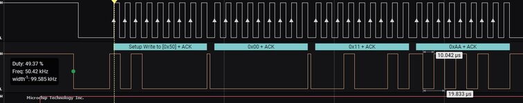
I2C__Write(MASTER_WRITE_24LC512_ADDRESS);
I2C__Write(0x00); //EEPROM`s address higher 8 bits (random number for testing)
I2C__Write(0x11); //EEPROM`s address lower 8 bits (random number for testing)
I2C__Write(0x49); //Writing random number to the EEPROM memory cell
I2C__Stop();
delay_ms(200);
LATAbits.LATA7 = 0;
}
}
return (EXIT_FAILURE);
}Attachments
Last edited by a moderator: