Continue to Site

Welcome to EDAboard.com

Welcome to our site! EDAboard.com is an international Electronics Discussion Forum focused on EDA software, circuits, schematics, books, theory, papers, asic, pld, 8051, DSP, Network, RF, Analog Design, PCB, Service Manuals... and a whole lot more! To participate you need to register. Registration is free. Click here to register now.

PIC18F4550 control battery charging

Status
Not open for further replies.

nmbg011

Member level 3
Joined
Oct 22, 2011
Messages
59
Helped
2
Reputation
4
Reaction score
2
Trophy points
1,288
Activity points
1,687
Hello,

I need source code in MikroC for PIC18F4550 which control 12V battery charging process.
Charger is 13,8V Float Charger at limited 5A.


Controler should do following:

1. Check battery voltage and if battery voltage less then 13,75V Turn On charger, and if battery voltage is 13,80 do nothing - stay off.

2. Charger charging battery and when voltage is 13,80V Turn off charger, and charger stay off, until battery voltage go less 12,72V, then charger cycle again.

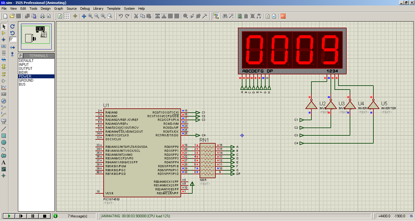
3. Four digit 7-seg LED display should show voltage in format example: 12.73

4. Second four digit 7-seg LED display current in 0-15A range. Current sensor is small value resistor 0,1mohm.

5. Charger is turned On/Off over Relay. Charger is independent circuit.

6. This control device will get power from charger circuit not from battery. When relay disconnect battery at full level, this device is powered over charger circuit, and continue to monitor battery voltage and current, until battery voltage goes under 12,72V.


Format of voltage on 4 7-seg led display (max 30V):
9.245
11.87
12.50
12.73
13.80

Format of current on 4 7-seg led siplay (max 15A)
0.100
0.555
1.145
5.500
9.732
10.00
15.00


If possibility exist to add one toggle taster which switch Ah/Current flow on second 4x 7-seg displays.
Example - in one state to show 40Ah _9Ah 14Ah 55Ah for 100Ah and more to show 100A
for second state to show current flow of amperage with previous descriptions. On end of cycle last value of Ah stand on 7-seg display like information for user.

One taster is needed for restarting of charging cycle.
 
Last edited:

If you're willing to write the code, I'm willing to help you if and when you are stuck - how to write it, what to consider, etc. I can help you in parts of the code if you're stuck. But I can't write your entire code for you.

Have you designed the hardware?
 
Circuit.png


VOLTMETER DISPLAY
=================
RA0 Fourth Digit
RA1 Third Digit
RA2 Second Digit
RA3 First Digit

RD0 A
RD1 B
RD2 C
RD3 D
RD4 E
RD5 F
RD6 G
RD7 DP


AMPERMETER DISPLAY
===================
RC0 4 digit
RC1 3 digit
RC2 2 digit
RC4 1 digit

RB0 A
RB1 B
RB2 C
RB3 D
RB5 E
RB6 F
RB7 G
I FORGOT FOR DP PIN PORT AND RESISTOR


ADC
=====
RA5 ANALOG IN VOLTMETER
RB4 ANALOG INPUT FOR CURRENT


STATUS AND CONTROL
===================
RC6 LED CHARGING CYCLE IS OVER
RC7 LED CHARGING IS ON
RE2 RESTART CHARGING CYCLE
RE1 RELAY OUTPUT
 

So, you should start coding.
Do you know how to use the ADC module? Do you know how to interface with 7-segment displays?

You should tackle each part separately, get them working and then put them all together.
 
Last edited:
Thank you mr. Tahmid for support,

I will start with coding. For first step I will try to make separated codes for each part of circuit.

See you soon...
 

Yes. You can find loads of examples of use of ADC, 7-segments, etc online. Go through them and start coding.
 

It's quite easy. You can find examples.

Try writing the program. I can help you with it.

- - - Updated - - -

As nmbg011 is going to use 18F4550, I decided to write this for the 18F4550.

This program counts from 0 to 9999 and then to 0 to 9999 over and over again. This is to demonstrate how to interface 4 7-segment displays to the PIC18F4550.

Here is the entire code:

Code:
void Send7(unsigned char Dig, unsigned char DigNo){
     unsigned char Dat;
     switch (DigNo){
            case 1:{
                 PORTC = 1;
                 break;
            }
            case 2:{
                 PORTC = 2;
                 break;
            }
            case 3:{
                 PORTC = 4;
                 break;
            }
            case 4:{
                 PORTC = 128;
                 break;
            }
     }
     switch (Dig){
            case 0:{
                 Dat = 0x3F;
                 break;
            };
            case 1:{
                 Dat = 0x06;
                 break;
            };
            case 2:{
                 Dat = 0x5B;
                 break;
            };
            case 3:{
                 Dat = 0x4F;
                 break;
            };
            case 4:{
                 Dat = 0x66;
                 break;
            };
            case 5:{
                 Dat = 0x6D;
                 break;
            };
            case 6:{
                 Dat = 0x7D;
                 break;
            };
            case 7:{
                 Dat = 0x07;
                 break;
            };
            case 8:{
                 Dat = 0x7F;
                 break;
            };
            case 9:{
                 Dat = 0x6F;
                 break;
            };
     }
     PORTD = Dat;
}

void main() {
     unsigned int i;
     unsigned char k;
     unsigned char j;
     unsigned char DG[4];
     PORTC = 0;
     PORTD = 0;
     TRISC = 0;
     TRISD = 0;
     ADCON1 = 0x0F; //All digital
     CMCON = 7; //Comparator off
     while (1){
           for (i = 0; i < 10000; i++){
               DG[0] = i / 1000;
               DG[1] = (i / 100) % 10;
               DG[2] = (i / 10) % 10;
               DG[3] = i % 10;
               for (k = 0; k < 7; k++){ //Adjust k as required
                   for (j = 0; j < 4; j++){
                       Send7(DG[j],j+1);
                       delay_ms(15); //Adjust this delay time
                   }
               }
           }
     }

}

It's quite simple actually.

This is the routine used for interfacing with the 7-segment displays.

Code:
void Send7(unsigned char Dig, unsigned char DigNo){
     unsigned char Dat;
     switch (DigNo){
            case 1:{
                 PORTC = 1;
                 break;
            }
            case 2:{
                 PORTC = 2;
                 break;
            }
            case 3:{
                 PORTC = 4;
                 break;
            }
            case 4:{
                 PORTC = 128;
                 break;
            }
     }
     switch (Dig){
            case 0:{
                 Dat = 0x3F;
                 break;
            };
            case 1:{
                 Dat = 0x06;
                 break;
            };
            case 2:{
                 Dat = 0x5B;
                 break;
            };
            case 3:{
                 Dat = 0x4F;
                 break;
            };
            case 4:{
                 Dat = 0x66;
                 break;
            };
            case 5:{
                 Dat = 0x6D;
                 break;
            };
            case 6:{
                 Dat = 0x7D;
                 break;
            };
            case 7:{
                 Dat = 0x07;
                 break;
            };
            case 8:{
                 Dat = 0x7F;
                 break;
            };
            case 9:{
                 Dat = 0x6F;
                 break;
            };
     }
     PORTD = Dat;
}

Here is the simulation result:

4154427300_1353945119.png


If you don't have any idea about 7-segments, don't try to use this code and start with it only. First read up a little on 7-segments. Then you can use and analyze this code.

Hope this helps.
Tahmid.
 

can i have the code of the control battery charging ??? please
 
Status
Not open for further replies.

Similar threads

Part and Inventory Search

Welcome to EDABoard.com

Sponsor

Back
Top