Continue to Site

Welcome to EDAboard.com

Welcome to our site! EDAboard.com is an international Electronics Discussion Forum focused on EDA software, circuits, schematics, books, theory, papers, asic, pld, 8051, DSP, Network, RF, Analog Design, PCB, Service Manuals... and a whole lot more! To participate you need to register. Registration is free. Click here to register now.

PIC18F4520 4 Digit 7 Segment using 74hc595 Shift Register

Status
Not open for further replies.

imranahmed

Advanced Member level 3
Joined
Dec 4, 2011
Messages
810
Helped
3
Reputation
6
Reaction score
3
Trophy points
1,298
Location
Karachi,Pakistan
Activity points
6,421
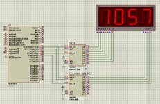
Please let me know I copied a code from internet for subject project and did some changing according to mikroC compiler, it is compiled and run successfully but only one digit is count-up not all other three digits are displaying. Do you know any other code or any link or hint. Two shift registers are used I attached here and also code is attached. Code is written in mikroC.
If I want to use common cathode display so what will changing required in column I also tried digits values in array for common cathode but not working.

Code:
#define SCLK  PORTC.B0         //Serial Clock
#define SDOUT PORTC.B1        //Serial Data Out
#define SDIN  PORTC.B2         //Serial Data In
#define CS0   PORTC.B3         //Chip Select
#define CS1   PORTC.B4
//---------------------------DIRECTION------------------------------------------
#define SCLK_dir   TRISC.B0
#define SDOUT_dir  TRISC.B1
#define SDIN_dir   TRISC.B2
#define CS0_dir    TRISC.B3
#define CS1_dir    TRISC.B4
//------------------------------------------------------------------------------

unsigned int size,offset,Rx,j,pos,count,temp, adc_value; //store output value from Analog Read function
char _data=0;
char* strNum[10];            //Character buffer (see itoa prototype)
//-------------------------Common Anode-----------------------------------------
                                // 0 , 1  ,  2 ,  3 ,  4 ,  5 ,  6 ,  7 ,  8 ,  9
unsigned const char digit[10] = {0xC0,0xF9,0xA4,0xB0,0x99,0x92,0x82,0xF8,0x80,0x90};
unsigned const char column[8] = {0x01,0x02,0x04,0x08,0x10,0x20,0x40,0x80};
unsigned const char noDigits = 4;

void SPI_init(void)
{
  SCLK_dir = 0;
  SDOUT_dir = 0;
  SDIN_dir = 1;
  CS0_dir  = 0;
  CS1_dir  = 0;
}
//--------------------------TX: transmit data-----------------------------------//
void SPI_write(char send)
{
  for(j=0;j<8;j++)
  {
    SCLK = 0;
    SDOUT = ((send << j) & 0x80) ? 1 : 0;   //MSB first.
    SCLK = 1;
  }
}
//--------------------------RX: recieve data------------------------------------//
char SPI_read(void)
{

  for(Rx = 0 ; Rx < 8 ; Rx++ )
  {
    SCLK = 0;
    _data += (SDIN << (7-Rx));  //MSB first.
    SCLK = 1;
  }

  return _data;
}

void SR_dataSend(char _data)
{
  CS0 = 0;
  SPI_write(_data);
  CS0 = 1;
}
//------------------------------------------------------------------------------
void SR_colSend(char col)
{
  CS1 = 0;
  SPI_write(col);
  CS1 = 1;
}
//------------------------------------------------------------------------------
void SR_colSelect(char col)
{
  SR_colSend(column[col]);    //Turn particular column On
  Delay_ms(5);
  SR_colSend(0);              //...then turn it Off
}
void segment_display(int number)
{

  IntToStr(number,strNum);    //Change from Int to C-String (stdlib function)

  size = strlen(strNum);               //<string.h> function
  offset = noDigits - size;

  for(pos=0; pos < size; pos++)
  {
    char index = strNum[pos] - 48;          //Decimal 48 is 0 in ASCII

    SR_dataSend(digit[index]);
    SR_colSelect(pos + offset);
  }
}


void main() {
ADCON0 = 0x00;
ADCON2 = 0x26;    //
OSCCON = 0x74;
// OSCTUNE = 0x40;   // osctune bit 6 is used to activate PLL for internal oscillator
TRISA  = 0x01;      /*set as input port*/
TRISC  = 0x00;

SPI_init();

while(1){

for(count=0; count<10000; count++)
    {
     segment_display(count);
     Delay_ms(20);
    }
count=0;
}
}
 

Attachments

  • SR_7Segment_Schematic.JPG
    SR_7Segment_Schematic.JPG
    119.4 KB · Views: 131
Last edited:

danadakk

Advanced Member level 5
Joined
Mar 26, 2018
Messages
2,296
Helped
351
Reputation
720
Reaction score
528
Trophy points
113
Activity points
10,090
For future reference there are processors out there that have all that
external HW inside them .....


Regards, Dana.
 

betwixt

Super Moderator
Staff member
Advanced Member level 7
Joined
Jul 4, 2009
Messages
15,792
Helped
5,085
Reputation
10,195
Reaction score
4,947
Trophy points
1,393
Location
Aberdyfi, West Wales, UK
Activity points
133,737
... but do note that the 74HC595 is NOT an LED driver and relying on it's limited drive/sink capability to protect it and the LEDs from damage is not a reliable solution.

Brian.
 

FvM

Super Moderator
Staff member
Advanced Member level 7
Joined
Jan 22, 2008
Messages
50,981
Helped
14,629
Reputation
29,534
Reaction score
13,738
Trophy points
1,393
Location
Bochum, Germany
Activity points
291,697
Post #1 is discussing two different problems. 1. Only one digit displaying, 2. you want to use CC display. What's your present problem?

Brad gave solution for second problem. If first problem is still pending, is it observed with CA or CC display? Which digit is shown? Did you debug the code by single stepping and looking at the generated output?

Comments about HC595 not being a suitable LED driver are correct, but irrelevant for Proteus simulation.
 

    imranahmed

    Points: 2
    Helpful Answer Positive Rating

KlausST

Super Moderator
Staff member
Advanced Member level 7
Joined
Apr 17, 2014
Messages
23,261
Helped
4,741
Reputation
9,503
Reaction score
5,126
Trophy points
1,393
Activity points
154,093
Hi,

Is it simulation or real device test?
"only one" ... but which digit is counting?
Which exact LED dsiplay are you using?

Klaus
 

    imranahmed

    Points: 2
    Helpful Answer Positive Rating

imranahmed

Advanced Member level 3
Joined
Dec 4, 2011
Messages
810
Helped
3
Reputation
6
Reaction score
3
Trophy points
1,298
Location
Karachi,Pakistan
Activity points
6,421
Post #1 is discussing two different problems. 1. Only one digit displaying, 2. you want to use CC display. What's your present problem?

Brad gave solution for second problem. If first problem is still pending, is it observed with CA or CC display? Which digit is shown? Did you debug the code by single stepping and looking at the generated output?

Comments about HC595 not being a suitable LED driver are correct, but irrelevant for Proteus simulation.
All displays are lit-up correctly now problem solved but only problem is trying to do with CC display, I changed segments values for CC but I think column array alsi needs to change with other values.

However, if anyone tell me how shift register is working here, there are two shift registers one for digit`s segments and other for digits.
Second shift register drives digits 1234 i.e Qa,Qb,Qc,Qd shift register output, if I want to change instead Qe,Qb,Qf,Qa how to do it.?
--- Updated ---

Hi,

Is it simulation or real device test?
"only one" ... but which digit is counting?
Which exact LED dsiplay are you using?

Klaus
It is simulation then I will transfer to original device.
Only one digit problem is solved but how to use CC display.
 

FvM

Super Moderator
Staff member
Advanced Member level 7
Joined
Jan 22, 2008
Messages
50,981
Helped
14,629
Reputation
29,534
Reaction score
13,738
Trophy points
1,393
Location
Bochum, Germany
Activity points
291,697
You can simply switch from CA to CC by inverting all output data,

e.g. change in SPI_write()
Code:
SDOUT = ((send << j) & 0x80) ? 1 : 0;
to
Code:
SDOUT = ((send << j) & 0x80) ? 0 : 1;
 

Aussie Susan

Advanced Member level 4
Joined
Jan 5, 2015
Messages
1,485
Helped
406
Reputation
812
Reaction score
443
Trophy points
1,363
Activity points
17,480
You have not said what LED display you are using but I'll be t dollars to doughnuts that the data sheet will tell you. Just picking the first Google result for '7 segment led display' shows that there is a 'DP' pin on that device. I suggest that you look at the pin descriptions in the data sheet for your display and see if there is something similar. The data sheet might even tell you how to use it!
Susan
 

imranahmed

Advanced Member level 3
Joined
Dec 4, 2011
Messages
810
Helped
3
Reputation
6
Reaction score
3
Trophy points
1,298
Location
Karachi,Pakistan
Activity points
6,421
Can anyone tell me how lit-up all digits as zero after count goes to zero from 9999.
0 should be display as 0000 and 57 should be display as 0057.

Code:
void segment_display(int number)
{

  IntToStr(number,strNum);    //Change from Int to C-String (stdlib function)
  str = strNum;
  size = strlen(str);               //<string.h> function
  offset = noDigits - size;
  for(pos=0; pos < size ; pos++)
  {
    index = str[pos] - 48;          //Decimal 48 is 0 in ASCII
    SR_dataSend(digit[index], pos + offset);
  }
}
 

KlausST

Super Moderator
Staff member
Advanced Member level 7
Joined
Apr 17, 2014
Messages
23,261
Helped
4,741
Reputation
9,503
Reaction score
5,126
Trophy points
1,393
Activity points
154,093
Hi,

The code of post#1 is no good coding style...with much nonsens in my opinion.
But your modified code of post#12 makes even less sense.

Thus I refer to the original code of post#1:

Code:
size = strlen(strNum);               //<string.h> function
This line tells how much digits to show.
size = 1: 1 digit for 0..9
size = 2: 2 digit for 10..99
size = 3: 3 digit for 100..999
size = 4: 4 digit for 1000..9999

with low modifcation effort just write:
Code:
size = 4;
instead. Then it always shows 4 digits.

***

But the much better way is: to learn how to write code on your own.
This does not mean that you should write every single line on your own. ... although you could.
But it helps to find out if the "copied code" is good or bad.

Klaus
 

imranahmed

Advanced Member level 3
Joined
Dec 4, 2011
Messages
810
Helped
3
Reputation
6
Reaction score
3
Trophy points
1,298
Location
Karachi,Pakistan
Activity points
6,421

Hi,

The code of post#1 is no good coding style...with much nonsens in my opinion.
But your modified code of post#12 makes even less sense.

Thus I refer to the original code of post#1:

Code:
size = strlen(strNum);               //<string.h> function
This line tells how much digits to show.
size = 1: 1 digit for 0..9
size = 2: 2 digit for 10..99
size = 3: 3 digit for 100..999
size = 4: 4 digit for 1000..9999

with low modifcation effort just write:
Code:
size = 4;
instead. Then it always shows 4 digits.

***

But the much better way is: to learn how to write code on your own.
This does not mean that you should write every single line on your own. ... although you could.
But it helps to find out if the "copied code" is good or bad.

Klaus
Thank oyu for reply,
I know coping is not good approach but I I am only stuck in Common Anode to Common Cathode conversion please let me know.
 

KlausST

Super Moderator
Staff member
Advanced Member level 7
Joined
Apr 17, 2014
Messages
23,261
Helped
4,741
Reputation
9,503
Reaction score
5,126
Trophy points
1,393
Activity points
154,093
Hi,

the correct answer is already given.
You have to write the code on your own. Or pay someone to do your job.

You can show your code and we will help you to rectify errors. (if we have a good error description)

Klaus
 

    imranahmed

    Points: 2
    Helpful Answer Positive Rating

imranahmed

Advanced Member level 3
Joined
Dec 4, 2011
Messages
810
Helped
3
Reputation
6
Reaction score
3
Trophy points
1,298
Location
Karachi,Pakistan
Activity points
6,421
Hi,

the correct answer is already given.
You have to write the code on your own. Or pay someone to do your job.

You can show your code and we will help you to rectify errors. (if we have a good error description)

Klaus
Code:
 #include "VALUES.h"
#define SCLK  PORTE.B0        //Serial Clock
#define SDOUT PORTA.B1        //Serial Data Out
#define CS0   PORTE.B1        //Chip Select

//---------------------------DIRECTION------------------------------------------
#define SCLK_dir   TRISE.B0
#define SDOUT_dir  TRISA.B1
#define CS0_dir    TRISE.B1

//------------------------------------------------------------------------------

unsigned int lit,size,offset,Rx,j,pos,count,temp, adc_value;   //store output value from Analog Read function
char _data = 0, index = 0;
char strNum[10];           //Character buffer (see itoa prototype)
char* str;
//-------------------------------------------------------------------------------
                                // 0 , 1  ,  2 ,  3 ,  4 ,  5 ,  6 ,  7 ,  8 ,  9
unsigned const char digit[11] = {0x3F,0x06,0x5B,0x4F,0x66,0x6D,0x7D,0x07,0x7F,0x6F,0x80}; // Common Cathode
unsigned const char column[4] = {0xBF,0xDF,0xEF,0xF7};
//unsigned const char digit[11] = {0xC0,0xF9,0xA4,0xB0,0x99,0x92,0x82,0xF8,0x80,0x90,0x7F}; // Common Anode
//unsigned const char column[4] = {0x40,0x20,0x10,0x08};
unsigned const char noDigits  = 4;

void SPI_init(void)
{
  SCLK_dir  = 0;
  SDOUT_dir = 0;
  CS0_dir   = 0;
}
//--------------------------TX: transmit data-----------------------------------//
void SPI_write(char send)
{
  for(j=0;j<8;j++)
  {
    SCLK = 0;
    SDOUT = ((send << j) & 0x80) ? 0 : 1;  //MSB first.
    SCLK = 1;
  }
}

void SR_dataSend(char _data, char col)
{
  CS0 = 0;
  SPI_write(column[col]);    //Turn particular column On
  SPI_write(_data);
  CS0 = 1;
}
//------------------------------------------------------------------------------
void segment_display(int number)
{
   if(number == 0) {
   for(lit=0 ; lit < 4 ; lit++)
   SR_dataSend(digit[0], lit);
   }else if(number > 0 && number <= 9)
   {
   for(lit=0 ; lit < 3 ; lit++)
   SR_dataSend(digit[0], lit);
   }
   else if(number >= 10 && number <= 99)
   {
   for(lit=0 ; lit < 2 ; lit++)
   SR_dataSend(digit[0], lit);
   }
   else if(number >= 100 && number <= 999)
   {
   for(lit=0 ; lit < 1 ; lit++)
   SR_dataSend(digit[0], lit);
   }

  IntToStr(number,strNum);    //Change from Int to C-String (stdlib function)
  str = strNum;
  size = strlen(str);               //<string.h> function
  offset = noDigits - size;
  for(pos=0; pos < size ; pos++)
  {
   index = str[pos] - 48;          //Decimal 48 is 0 in ASCII
   SR_dataSend(digit[index], pos + offset);
   SR_dataSend(digit[10], 0x02);
  }
}

long map(long x, long in_min, long in_max, long out_min, long out_max) {
  return (x - in_min) * (out_max - out_min) / (in_max - in_min) + out_min;
}

void main() {
 ADCON0 = 0x00;
 ADCON2 = 0x26;
 //OSCCON = 0x74;
 //OSCTUNE = 0x40;   // osctune bit 6 is used to activate PLL for internal oscillator
 TRISA  = 0x01;      /* set as input port */
 TRISE  = 0x00;
 SPI_init();
 ADC_Init_Advanced(_ADC_INTERNAL_REF);
 PWM1_Init(19400);        // Initialize PWM1 module at 5KHz
 PWM1_Start();            // start PWM1
 PWM1_Set_Duty(0);        // Set current duty for PWM1
 while(1){
   temp = ADC_Get_Sample(0);
   temp = map(temp, 0, 1023, 0, 211);
   if(temp >= 0 && temp <= 211){
   adc_value = VALUES[temp];
   PWM1_Set_Duty(VALUES[temp]);        // Set current duty for PWM1
   segment_display(adc_value);
   }
 }
}
I think only sone changes will be made in SPI_Write function and SR_dataSend, I changed or inverted char array of digits already
 

Aussie Susan

Advanced Member level 4
Joined
Jan 5, 2015
Messages
1,485
Helped
406
Reputation
812
Reaction score
443
Trophy points
1,363
Activity points
17,480
I'm also confused. In the schematic, you show what you call the SH_CP signal (SRCLK on the 75HC595) going to the RC0 pin, but your code refers the SCLK signal (which I think is the same thing - it always makes things clearer if you use consistent naming convention) on RE0 which the schematic show floating.
Also, the shift register requires some use of the RCLK pin to move the data from the shift registers to the storage registers for output, but I can't see that in the code.
My concern with your SPI_write function is that the 'SCLK=1;' operation is almost immediately followed by the next 'SCLK=0;' operation after looping via the 'for' loop. Depending on the clock speed, you may or may not meet the shift registers minimum pulse width (either high or low) of 20nS.
The MCU you are using has a perfectly good MSSP module that can do all of the hard work for you - why bit-bang the SPI interface when you don't need to.
Susan
 

Status
Not open for further replies.

Part and Inventory Search

Welcome to EDABoard.com

Sponsor

Top