Continue to Site

Welcome to EDAboard.com

Welcome to our site! EDAboard.com is an international Electronics Discussion Forum focused on EDA software, circuits, schematics, books, theory, papers, asic, pld, 8051, DSP, Network, RF, Analog Design, PCB, Service Manuals... and a whole lot more! To participate you need to register. Registration is free. Click here to register now.

[SOLVED] PIC16F8870 & RS232 RFID READER & Mikro C

Status
Not open for further replies.
Hi, want ask something related to external crystal.
Can we really measure external crystal output from oscilloscope?
Does baud rate affected by the crystal output frequency from pin RA7 ?
Because I tested hardware with pic16F8867, the LCD outputs shows strange character after few tag near to the reader.
I have used simulation ISIS to test it, it's working.

PIC clock speed : 20MHz
External Crystal speed: 20MHz.

Anyone know how to solve this ?
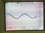
 

Hi, so far I tested the hardware, the LCD display doesn't show correct character/number of RFID reader with PIC16F887.
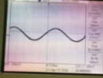
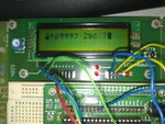
Here's the result :
210920112329.jpg210920112330.jpg210920112331.jpg

From diagram above, there are two sine diagram (approximately 38-39MHz) from oscilloscope which measure output from RA7 & RA6 with parallel capacitor of 30pF/ 15pF.
Here's my MikroC project properties clock oscillators.
1.JPG

And if I select other properties for clock oscillator, there isn't any outputs sine wave from oscilloscope.

Anyone suggest opinion how can this happen ?
 

I'm attached another RFID specifications:
RFID 1.JPGRFID spec.JPG

I'm confused with start bit and end bit here.
Does it mean RFID reader sent 12 characters ?
 

Guys,

I have managed get the result from MikroC terminal with proper RFID tag ID however my LCD display 16x2 still cant show correct characters.
Attachments below are
1.my RFID tag ID:
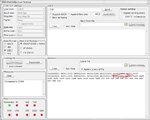
2.MikroC Terminal Result : Binaries, Hex, ASCII (highlighted red color circle)
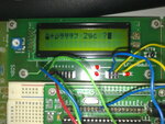
3.LCD display output: Weird characters

250920112334.jpgresult terminal.JPG
210920112331.jpg


Regards
Linspire
 

I'm confused with start bit and end bit here.
Does it mean RFID reader sent 12 characters ?

Each successful read sends 12 bytes of ASCII data, the first ASCII byte is nondisplayable Start of Heading (0x01), followed by 10 bytes of ASCII characters representing the RFID, and finally an ASCII byte, also nondisplayable, Start of Text (0x02) is sent.

**broken link removed**

BigDog

---------- Post added at 05:00 ---------- Previous post was at 04:55 ----------

I have managed get the result from MikroC terminal with proper RFID tag ID however my LCD display 16x2 still cant show correct characters.

Is this with the RFID Reader connected directly to your RS-232 USB converter?

1.my RFID tag ID:
2.MikroC Terminal Result : Binaries, Hex, ASCII (highlighted red color circle)
3.LCD display output: Weird characters

Does your LCD display string literals correctly in your application? In other words are the RFIDs the only "weird" ASCII data being displayed by the LCD?

BigDog
 

Is this with the RFID Reader connected directly to your RS-232 USB converter?

Nope. I measure from my customized made max232 converter's output. Input max232 is RFID-232.
Output voltage of mine max232 converter is around 3V.

Does your LCD display string literals correctly in your application? In other words are the RFIDs the only "weird" ASCII data being displayed by the LCD?

I have tested simple testing LCD display, from user manual mikroC example. It's working properly. Just RFID reader , I suppose.


Regards
Linspire
 
Last edited:

Nope. I measure from my customized made max232 converter's output. Input max232 is RFID-232.
Output voltage of mine max232 converter is around 3V.

I have tested simple testing LCD display, from user manual mikroC example. It's working properly. Just RFID reader , I suppose.

The RFID reader according to its documentation provides a RS-232 interface and obviously the RS-232/USB converter has a RS-232 interface.

So why are you using your custom MAX232 between the two devices?

And more importantly, if you are still able to receive ASCII data with your custom MAX232 installed, it would seem to indicate your custom MAX232 doesn't function as expected.

Frankly, I question the logic of rather than using a MAX232, which is readily available worldwide, you have chosen to build a custom circuit instead, thereby introducing another point of failure in your design.

I would strongly suggest you pickup a MAX232 and a handful of appropriate capacitors as indicated in the devices datasheet and use a known RS-232 Transceiver in place of your custom device.

Obviously the issue in not the LCD, but the UART and its associated RS-232 connection with the RFID Reader. If the UART is properly initialized for the PICs oscillator frequency, then the only other possibility is the RS-232 transceiver, your custom device.

You could easily test the PIC side of the RS-232 setup by performing a loopback test, like you have previously the RS-232/USB converter, and displaying the results on the LCD.

BigDog


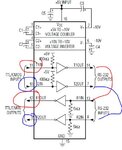
Last week, I have try connect few MAX232s with schematic below which doesnt give any outputs at all.
RFID_connection.JPG
That's why I built one.
Can you helped me checked whether this schematic got problem ?

Regards
Linspire
 

There a several issues, there should be five 1uF capacitors, I count only four in your schematic.

Also the corresponding TTL output for pin 13 RS-232 input is pin 12 not pin 11.

I have attached a schematic for a typical MAX232 circuit to help you with the capacitor issue:

MAX232.jpg

Reference **broken link removed**

Try correcting the above issues and see if this improves your RS-232 communications.


BigDog
 

I tested them.
Still weird character output from LCD display 16x2.

Regards
Linspire
 

Then most likely it is your UART initialization. Is the latest version of your app posted in this thread?

Using the MAX232 perform a loopback test on the PIC side. Send a few characters to the LCD and UART, then display the characters received by the loopback as well.

BigDog
 

How to make loop test for PIC ?

Regards
Linspire
 

Simple.

Display a short string literal "test" on the LCD, then send the same string through the UART one character at a time while storing the received characters in a buffer which you will also display on the LCD.

Short the RS-232 TX/RX pair on the MAX232 to create a loopback.

What is your current crystal/oscillator frequency? Where can I find the latest version of your program?

BigDog
 

Here's my project file.
View attachment UART_LCD_PIC16F887.rar

Here's my coding:
Code:
unsigned char uart_rd;
unsigned char data;
unsigned char temp[13];
unsigned char N = 0;

// LCD define
// Lcd pinout settings
sbit LCD_RS at RB4_bit;
sbit LCD_EN at RB5_bit;
sbit LCD_D7 at RB3_bit;
sbit LCD_D6 at RB2_bit;
sbit LCD_D5 at RB1_bit;
sbit LCD_D4 at RB0_bit;

// Pin direction
sbit LCD_RS_Direction at TRISB4_bit;
sbit LCD_EN_Direction at TRISB5_bit;
sbit LCD_D7_Direction at TRISB3_bit;
sbit LCD_D6_Direction at TRISB2_bit;
sbit LCD_D5_Direction at TRISB1_bit;
sbit LCD_D4_Direction at TRISB0_bit;


void main() {
   TRISC = 0x80;

   OSCCON = 0x76;
  OSCTUNE = 0x0F ;
   ANSEL  = 0;                        // Configure AN pins as digital I/O
   ANSELH = 0;
   C1ON_bit = 0;                      // Disable comparators
   C2ON_bit = 0;
   TRISB = 0;
   PORTB = 0xFF;
   UART1_Init(9600);
   Delay_ms(100);

   Lcd_Init();
   Lcd_Cmd(_LCD_BLINK_CURSOR_ON);
   //Lcd_Cmd(_LCD_CLEAR);
   //Lcd_out(1,1,"Testing");
   Delay_ms(1000);


   do {
   if (UART1_Data_Ready()){              //<------ Check if a character has been received before reading
       uart_rd = UART1_Read();     // read the received data,
       UART1_Write(uart_rd);

       temp[N] = uart_rd;

       N = N +1;

       if (N == 12) // temp storing  string
       {
          temp[12] = 0;
          Lcd_Cmd(_LCD_CLEAR);
          Lcd_out(1,1,temp);
          N=0;
        }

       }
    } while(1);
}

I have tried external crystal 20Mhz, internal 8Mhz, all same results before.

Linspire
 

short loop.JPG
Are you saying these kind of short TX/RX ?

Linspire
 

Yes. But you only need one set either T1/R1 or T2/R2, you only have one pair of TX/RX lines coming from the PIC.

BigDog
 

Erm..how to write this simple test coding.


Linspire

---------- Post added at 15:31 ---------- Previous post was at 15:16 ----------

Code:
   TRISC = 0x80;
   OSCCON = 0x76;
   OSCTUNE = 0x0F ;
   ANSEL  = 0;                        // Configure AN pins as digital I/O
   ANSELH = 0;
   C1ON_bit = 0;                      // Disable comparators
   C2ON_bit = 0;
   TRISB = 0;
   PORTB = 0xFF;
   UART1_Init(9600);
   Delay_ms(100);

   Lcd_Init();
   Lcd_Cmd(_LCD_BLINK_CURSOR_ON);
   Lcd_out(1,1,"Testing");
   Delay_ms(1000);
   Lcd_Cmd(_LCD_CLEAR);
   Lcd_Cmd(_LCD_BLINK_CURSOR_ON);
   do{
   if(UART1_DATA_Ready()){
    UART1_Write(temp);
    data1 = UART1_Read();
    LCD_chr_CP(data1);
   }  }
   while(1);

My LCD display didn't display anything for this coding instead "Testing initially".

Linspire
 

I seem to remember you writing a similar UART routine and posting sometime back in this or another one of your discussion threads.

BigDog
 

Yap, I didn't add much changes of my coding.
Therefore, you seem similarity coding I posted.

Linspire
 

My LCD display didn't display anything for this coding instead "Testing initially".

Ok.

Now remove the MAX232 and short the TX/RX lines of the PIC. If your routine is written correctly this should echo back any character sent regardless of BAUD rate or other settings.

Actually, I was referring to specifically a loopback routine similar to this situation. Haven't we done this before?

BigDog
 

Status
Not open for further replies.

Similar threads

Part and Inventory Search

Welcome to EDABoard.com

Sponsor

Back
Top