Continue to Site

Welcome to EDAboard.com

Welcome to our site! EDAboard.com is an international Electronics Discussion Forum focused on EDA software, circuits, schematics, books, theory, papers, asic, pld, 8051, DSP, Network, RF, Analog Design, PCB, Service Manuals... and a whole lot more! To participate you need to register. Registration is free. Click here to register now.

[SOLVED] pic16f877a+compare capture pulse width modulation +sample coding

Status
Not open for further replies.

manikandanshine

Full Member level 1
Joined
Aug 15, 2012
Messages
99
Helped
7
Reputation
14
Reaction score
7
Trophy points
1,298
Location
india
Activity points
1,809
i studied basic concept about ccp module.but i want is,where this module can be used.anybody have sample coding.plz post it......


thanks in advance....
 

You may have already read this, but I'll just say it again.

CCP consists of 3 parts as the name suggests:
Capture Compare PWM

So, these 3 parts are used for 3 different functions.
What I use most is the PWM portion. However, what you use will depend on your requirements.

Which compiler do you use?
 

Here is an example (mikroC) employing the PWM part of the CCP1 module:

Code:
void main() {
     PORTC = 0;
     TRISC = 0;
     PR2 = 249; //4kHz frequency of PWM @ 4MHz clock
     CCPR1L = 62; //~25% duty cycle
     CCP1CON = 0x0C; //PWM mode
     TMR2ON_bit = 1; //Turn Timer 2 on
     
     while(1);
}
You should know that the 16F877A has 2 CCP modules - CCP1 and CCP2. I've used CCP1 in the above code and have used the PWM mode.

For CCP1, you select the PWM mode through the CCP1CON register (CCP2CON for CCP2). Refer to CCP section (page 66) of the 16F877A datasheet. Bits 0 to 3 set the mode of operation. Setting bits 3 and 2 to 1 set the mode to PWM (what you set for bits 0 and 1 doesn't matter for PWM mode). I've set CCP1CON to 12 in the code above (PWM mode - bits 3 to 0: 1100).

PR2 sets the frequency. PR2 is the period register and it uses Timer 2 for the time base. You should keep in mind that even though you have 2 CCP modules, both modules use Timer 2 as the time base for PWM mode and both use PR2 for the period register.

The formula relating PWM period and PR2 is:

PWM Period = [(PR2) + 1] • 4 • TOSC • (TMR2 Prescale Value)

CCPR1L is used to set the duty cycle (for CCP1). Ratio of CCPR1L to PR2 gives the duty cycle.

I hope I could help make this clear for you.

Hope this helps.
Tahmid.
 
Last edited:

Hi Tahmid-

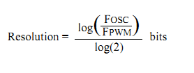
I have doubt in PWM resolution? I need 7bit resolution in 156khz. how to check this?
 

You can check using the formula (obtained from datasheet):
5142875900_1348658945.png


Hope this helps.
Tahmid.
 

ya. its OK... But i didn't vary the duty cycle in 0 to 127.

above 60 duty cycle value, High output will come. didn't change anything.what is the problem?
 

ya. its OK... But i didn't vary the duty cycle in 0 to 127.

above 60 duty cycle value, High output will come. didn't change anything.what is the problem?

Which code are you referring to? Is 60 the value of CCPR1L? What's the value assigned to PR2?
 

freq=156khz
PR2=0x1F;
Resolution=7;
What is the meaning of resolution?
 

PR2 = 0x1F = 31

You can think of the resolution as indicative of the number of steps you can control the PWM with. "Resolution = 7" means 7-bit control. The least significant 2 bits are "decimal-place" bits. So, the resolution is actually 5. This means that you can control the PWM in 2^5 = 32 steps.

Since PR2=31, you can only control it in 32 steps (0 to PR2+1). So, that's 5-bit control as you already know.

Now, it's called 7-bit resolution taking the decimal places into consideration. The decimal places set 0, .25, .5 and .75. So, that's four additional steps. 32*4 = 128. 7-bit -> 2^7 = 128.

Hope this helps.
Tahmid.
 
I need to vary 128 level.. how to vary it

- - - Updated - - -

I need changing level 0 to 128 bit,

How to input gives to CCPR1L?1=1bit,2=2bit,3=3bit and 128=128bit?
 

Since you have PR2=31, and you have overall 7-bit control, you can vary 128 levels.

CCPR1L varies between 0 and 31. The decimal places are set through bits 5 and 4 of the CCP1CON register. Setting bits 5 and 4 sets the decimal places as such:
00 - .0
01 - .25
10 - .5
11 - .75

So, alongside CCPR1L, also adjust the values of bits 5 and 4 of CCP1CON to achieve 128-step control (7-bit resolution).

Hope this helps.
Tahmid.
 

Thanks:) Pls explain little more

- - - Updated - - -

Input is 00 to 7F? How to divide the no?

- - - Updated - - -

Give any examples?

- - - Updated - - -

Value=data & 0b00110000;
CCP1CON=Value | 0b00001100;

data=data/4;
CCPR1L=data;


its right or not?
 

You have PR2 = 31. And you want control in 128 steps (which is the maximum you can get).

Each step is 0.25. So, you can have values of control like 0.0,0.25,0.5,0.75,........30.0,30.25,30.5,30.75.

So, data values vary from 0 to 127.

Code:
CCPR1L = data >> 2; //CCPR1L = data/4;
modo = data % 4; // either 0, 1, 2 or 3

modo = modo << 4;
CCP1CON = 0b00001100 | modo;

Hope this helps.
Tahmid.
 

    V

    Points: 2
    Helpful Answer Positive Rating
Thank you very much.... I got it..
 

Status
Not open for further replies.

Similar threads

Part and Inventory Search

Welcome to EDABoard.com

Sponsor

Back
Top