T3STY
Full Member level 4
Hello everybody!
I'm new here and I hope we'll go on well")
I've come here because I'm working on a project with a PIC 16F84 which I'd like to use to control a 2x16 chars LCD display (Hitachi HD44780 driver). I'm programming in C as I have already programmed in this language and I know most of it. But this is my first time in PIC programming and I need some help...
What I need to know for now it's how to proceed in initializing the display for 4-bit data transfer and how to write chars on the display.
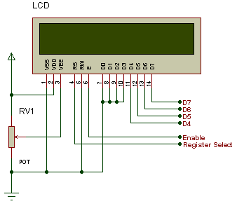
On the PIC I'd like to use PORT_A pins to drive the LCD. I see that the LCD uses E (enable), RS (register select) and R/W (Read/Write) pins. Is there any way I can pre-set them to not waste pins on the PIC? I've been thinking I could set E=VDD and R/W=GND (always enabled and writing), so I could use RA1-RA4 as LCD data and RA0 as RS. I don't need to read from LCD so it's ok to not be able to read from.
For testing I have MPLAB with Hi-Tech C Compiler and Proteus ISIS for hardware simulation; both have been tested and are working fine.
I hope you can help me, and thanks
I'm new here and I hope we'll go on well
I've come here because I'm working on a project with a PIC 16F84 which I'd like to use to control a 2x16 chars LCD display (Hitachi HD44780 driver). I'm programming in C as I have already programmed in this language and I know most of it. But this is my first time in PIC programming and I need some help...
What I need to know for now it's how to proceed in initializing the display for 4-bit data transfer and how to write chars on the display.
On the PIC I'd like to use PORT_A pins to drive the LCD. I see that the LCD uses E (enable), RS (register select) and R/W (Read/Write) pins. Is there any way I can pre-set them to not waste pins on the PIC? I've been thinking I could set E=VDD and R/W=GND (always enabled and writing), so I could use RA1-RA4 as LCD data and RA0 as RS. I don't need to read from LCD so it's ok to not be able to read from.
For testing I have MPLAB with Hi-Tech C Compiler and Proteus ISIS for hardware simulation; both have been tested and are working fine.
I hope you can help me, and thanks