Continue to Site

Welcome to EDAboard.com

Welcome to our site! EDAboard.com is an international Electronics Discussion Forum focused on EDA software, circuits, schematics, books, theory, papers, asic, pld, 8051, DSP, Network, RF, Analog Design, PCB, Service Manuals... and a whole lot more! To participate you need to register. Registration is free. Click here to register now.

[SOLVED] PIC16F716 Oscillator Problem - Simple LED Blink

Status
Not open for further replies.

Mywk

Newbie level 5
Joined
Apr 2, 2012
Messages
8
Helped
0
Reputation
0
Reaction score
0
Trophy points
1,281
Activity points
1,350
Hey all, new here so please no flaming just because I'm newbie in what concerns to electronics, I'm just a programmer trying to learn.

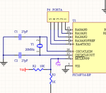
16V -> Diode -> 5V Voltage regulator -> Pic VDD
4Mhz Oscillator I found from spare parts correctly connected to port 16/15
Led + to Port B2

Here is the code I'm using:
Code:
#include <16F716.h>
#fuses XT,NOWDT, NOBROWNOUT
#use delay(clock=4000000)

#byte PORTB = 6 // PIC16F62X Data Sheet, Bank0

void main(void)
{
 set_tris_b(0);
 PORTB = 0;
 
 while( 1 )
 {
  output_high(PIN_B2);
  delay_ms(200);
  output_low(PIN_B2);
  delay_ms(200);
 }
}

It sometimes did work when I had my finger above the Microcontroller (static?), but since i tried 3 different ones I don't think that is the problem.


I tried to use a PIC16F628 and it works without any problem, basically same ports/connections, here is the 628 code:
Code:
#include <16F628.h>
#FUSES NOWDT,NOPUT,NOBROWNOUT,NOMCLR,NOLVP,XT  //INTRC_IO (Not using internal clock)
#use delay(clock=4000000)

#byte PORTB = 6 // PIC16F62X Data Sheet, Bank0

void main(void)
{
 setup_comparator(NC_NC_NC_NC);
 setup_vref(FALSE);
 set_tris_b(0);
 PORTB = 0;
 
 while( 1 )
 {
  output_high(PIN_B2);
  delay_ms(200);
  output_low(PIN_B2);
  delay_ms(200);
 }
}

What could be the problem? Maybe the configuration of the Fuses?

Thanks In Advance!
 

Along with the crystal, connected to the GND, two ceramic capacitors (of approximately 22 - 27 pF) will be required for this job. See details:
 

Attachments

  • schematic.png
    schematic.png
    9.6 KB · Views: 136

Along with the crystal, connected to the GND, two ceramic capacitors (of approximately 22 - 27 pF) will be required for this job. See details:

I completely forgot to say that I already have two 25pF capacitors correctly attached to the circuit, otherwise I think it would not even work with the PIC628 right?

--Edit: Just noticed, sometimes I plug it to power and it runs for like 3~4 seconds, then stops.
 
Last edited:

What about MCLR (pin 4) connected to the VDD via a small 10k resistor?

---------- Post added at 23:14 ---------- Previous post was at 23:11 ----------

And by the way, to protect the PIC use a series resistor for the LED. (100- 220 ohms)
 
  • Like
Reactions: Mywk

    Mywk

    Points: 2
    Helpful Answer Positive Rating
I added a 200ohm resistor before the led not to burn it just now.

That worked like a charm!! Why?
Also, is the 10k resistor really needed between MCLR and VDD? Why?

Thanks, that was a great help!
 

MCLR requires a high state to work and low state for reset the micro... with no pull-up (10kohm to VDD) it's in no definite state so with your finger it goes to high or not... mostly static and so....

---------- Post added at 17:11 ---------- Previous post was at 17:06 ----------

never forget to set a pull-up to MCLR, VDD to 5V GND to 0V the crystal

and also a common led works with 2.4V 5mA (not exact data but it works) so if you give it 5V it's certainly it will be burned or at least will heat... with a 200ohm resistor you limit the current to almost 13mA (5-2.4 = 2.6/200ohm == 13mA just a little high) but also it depends on your Led, i would set a 330ohm or higher (up to 1K) resistor for any led in my circuits...

---------- Post added at 17:12 ---------- Previous post was at 17:11 ----------

aaaannnnd also Don't forget that a common IO pin in a PIC at most can draw or source 20mA of current... so don't push it too far....
 
  • Like
Reactions: Mywk

    Mywk

    Points: 2
    Helpful Answer Positive Rating
Thank you all, very useful, replaced my 200ohm led resitor with a 1k one, also MCLR doesn't seem to do anything different whenever I use the 10k resistor, a 400ohm resistor or directly connected.. Then what do you mean with the high/low state?

Thanks once again!
 

MCLR/VPP = MCLR and VPP are two functions on the same pin;

MCLR means Master Clear, and functions as the Reset pin on the PIC micro, causing the PIC to be held in a reset state as long as MCLR is at 0 volts. When MCLR is connect to VDD instead, then the PIC begins running by executing the first instruction in program memory.

VPP means Voltage for Programming. When there are 9-12V ( need to see the specific datasheet) on this pin, the PIC goes into a special reset state where it's not running, but it can be programmed.
 
  • Like
Reactions: Mywk

    Mywk

    Points: 2
    Helpful Answer Positive Rating
MCLR/VPP = MCLR and VPP are two functions on the same pin;

MCLR means Master Clear, and functions as the Reset pin on the PIC micro, causing the PIC to be held in a reset state as long as MCLR is at 0 volts. When MCLR is connect to VDD instead, then the PIC begins running by executing the first instruction in program memory.

VPP means Voltage for Programming. When there are 9-12V ( need to see the specific datasheet) on this pin, the PIC goes into a special reset state where it's not running, but it can be programmed.

right!

it's always recommended to put a pull-up resistor at MCLR, you can use a higher res up to 47kohm or lower even directly to VDD

but

if you plan to put a RESET push button, you can´t put MCLR directly to VDD, so it should have a pull-up ressistor... this resistor shouldn't be too low so the current while pressing the button shouldn't be too much...

also leaving it with no pull-up could make it very vulnerable to static and noise...
 
  • Like
Reactions: Mywk

    Mywk

    Points: 2
    Helpful Answer Positive Rating
Status
Not open for further replies.

Part and Inventory Search

Welcome to EDABoard.com

Sponsor

Back
Top