Continue to Site

Welcome to EDAboard.com

Welcome to our site! EDAboard.com is an international Electronics Discussion Forum focused on EDA software, circuits, schematics, books, theory, papers, asic, pld, 8051, DSP, Network, RF, Analog Design, PCB, Service Manuals... and a whole lot more! To participate you need to register. Registration is free. Click here to register now.

[PIC] PIC16F688 ADC Non Linear

Status
Not open for further replies.

hamid159

Full Member level 3
Joined
Aug 25, 2013
Messages
176
Helped
14
Reputation
28
Reaction score
14
Trophy points
1,298
Location
Lahore
Activity points
2,488
Hi everyone,
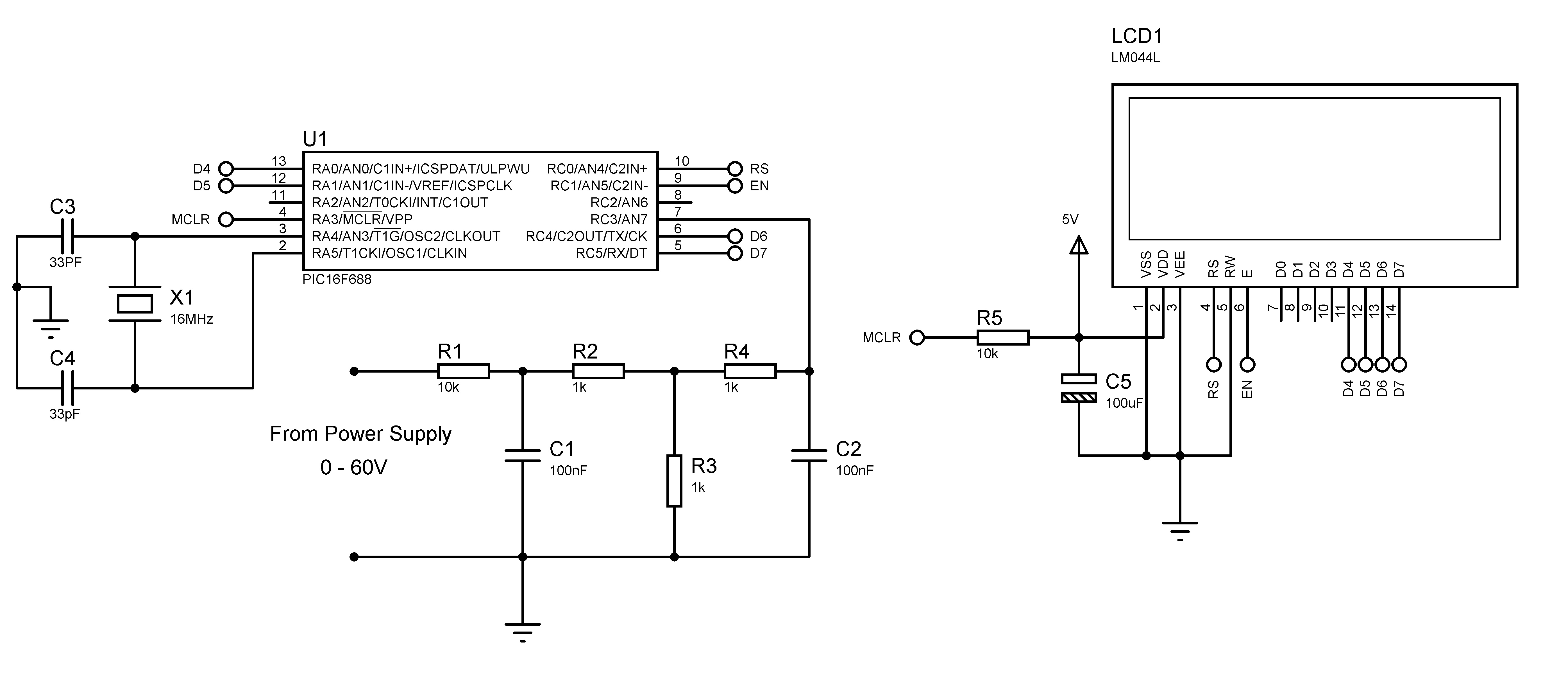
I was checking ADC of PIC16F688 and found it is not linear. The impedance seen by ADC was 1k. There was average step change of 5 (of ADRESH AND ADRESL register) even Potentiometer was dividing voltage equally (checked by UNI-T UT203 voltmeter). Reading of ADC result was 960 (constant) between 4.63 and 4.71V. How it could be possible? Is the PIC microcontroller faulty? or it is natural behaviour of PIC uC.

Voltage given to ADC was from UNI_T 9V battery.
 

More information needed!

How is the ADC configured and what voltage reference are you using. The PIC ADC circuits are usually very reliable.

Brian.
 

DO a linear sweep and map out all errors using a DAC output to scope comparing In-Out vs In in XY Mode

If the deadzones are repeating at bit boundaries it is due to hysteresis caused by poor groundshift or coupling of logic levels to Vref.

960 = 11 1100 0000
959 = 11 1011 1111

if the 6 LSB's cause a sift in Vref or the analog ground shared with digital ground or has some RF on either, it may get rectified creating a DC offset caused by logic level.

Check your currents on Vin and Vref for suspicious correlation . If current is excessive, the device may have been damaged by ESD or your layout is poor.
 

Voltage given to ADC was from UNI_T 9V battery

so you have a resitor network divider ..
9V -- R serial --- Potentiometer ---- 0V
curseur ------------------> ADC input
what is the value of R serial ? 820 ohms ?
Does the 9V battery voltage keep constant when you move the potar cursor
How do you convert Points to Volts ?
 

....and make sure the ADC input voltage never exceeds VDD. If you use the potentiometer across the 9V battery the voltage over nearly half the rotation will be higher than the PIC can handle and it could be damaged.

Brian.
 

so you have a resitor network divider ..
9V -- R serial --- Potentiometer ---- 0V
curseur ------------------> ADC input
what is the value of R serial ? 820 ohms ?
Does the 9V battery voltage keep constant when you move the potar cursor
How do you convert Points to Volts ?


:!:potar supposed value of 1K !
 

I only had the potentiometer before ADC, one terminal to 9V and other terminal to Gnd . Center terminal to ADC. I made sure i would never exceed the 1023.
I was using three ADC channels and was suffering this problem (non-linear). I dont know why. But then i changed the code for only one ADC channel. and found it was linear. Actually, i have to show voltage, current and current limit on LCD. So, i need three ADC channels. Now the problem is that even i use only one ADC, the ADC result is not constant at voltage greater than 3V (ADC pin voltage) approx. It is fluctuating 3 to 4 digits up and down.
Here is the circuit diagram.


AND code.
Code:
                              // LCD module connections
sbit LCD_RS at RC0_bit;
sbit LCD_EN at RC1_bit;
sbit LCD_D4 at RA0_bit;
sbit LCD_D5 at RA1_bit;
sbit LCD_D6 at RC4_bit;
sbit LCD_D7 at RC5_bit;

sbit LCD_RS_Direction at TRISC0_bit;
sbit LCD_EN_Direction at TRISC1_bit;
sbit LCD_D4_Direction at TRISA0_bit;
sbit LCD_D5_Direction at TRISA1_bit;
sbit LCD_D6_Direction at TRISC4_bit;
sbit LCD_D7_Direction at TRISC5_bit;
// End LCD module connections


char look(int a)
{
   switch(a)
   {
       case 0:
              return '0';
       case 1:
              return '1';
       case 2:
              return '2';
       case 3:
              return '3';
       case 4:
              return '4';
       case 5:
              return '5';
       case 6:
              return '6';
       case 7:
              return '7';
       case 8:
              return '8';
       case 9:
              return '9';
       default:
              return '.';
   }
}


void main()
{

unsigned int k = 0;  // stores ADC result for voltage
unsigned int count;  // used in average loop


  CMCON0.CM2 = 1;
  CMCON0.CM1 = 1;
  CMCON0.CM0 = 1;
  TRISA0_bit = 0;
  TRISA1_bit = 0;
  TRISA2_bit = 1;
  ANSEL = 0x80;     // AN7
  ADCON1 = 0x00;    //  Fosc/2
  ADCON0 = 0x81;    // Vref is VDD
  TRISC = 0x0C;     
  Lcd_Init();
  Lcd_Cmd(_LCD_CLEAR);
  LCD_Cmd(_LCD_CURSOR_OFF);

  do
  {

   k = 0;
count = 0;
while(count<64) {
      k = k + ADC_Read(0);
      k = ADC_Read(7);
      count++;
}
k = k >> 6;

LCD_Chr(1,1,look(k/1000));    // Display First Digit
k = k % 1000;
LCD_Chr_CP(look(k/100));     // Display Second Digit
k = k % 100;
LCD_Chr_CP(look(k/10));      // Display Third Digit
LCD_Chr_CP(look(k%10));      // Display Fourth Digit

Delay_ms(550);

  } while(1);
}

- - - Updated - - -

I think the noise from Power Supply is causing the fluctuation. I saw the noise at scope. I think at voltage greater than 3V, noise peak is effective ans causing the disturbance. Is there a way to reduce that noise?

PS: Power Supply is Switch Mode.
 

I was using three ADC channels and was suffering this problem (non-linear). I dont know why. But then i changed the code for only one ADC channel. and found it was linear. Actually, i have to show voltage, current and current limit on LCD. So, i need three ADC channels. Now the problem is that even i use only one ADC, the ADC result is not constant at voltage greater than 3V (ADC pin voltage) approx. It is fluctuating 3 to 4 digits up and down.

All channels are multiplexed to the same ADC module, therefore I suspect the ADC section of the microcontroller is not at fault.

Here is the circuit diagram.

I would recommend replace the resistor network you implemented for the power supply with a proper linear voltage regulator and filter cap. Doing so would provide better voltage regulation and eliminate the majority of noise for SMPS, such design techniques are often employed when SMPS are utilized to power digital based circuits, particularly ADC and DAC sections.

AND code.
Code:
                              // LCD module connections
sbit LCD_RS at RC0_bit;
sbit LCD_EN at RC1_bit;
sbit LCD_D4 at RA0_bit;
sbit LCD_D5 at RA1_bit;
sbit LCD_D6 at RC4_bit;
sbit LCD_D7 at RC5_bit;

sbit LCD_RS_Direction at TRISC0_bit;
sbit LCD_EN_Direction at TRISC1_bit;
sbit LCD_D4_Direction at TRISA0_bit;
sbit LCD_D5_Direction at TRISA1_bit;
sbit LCD_D6_Direction at TRISC4_bit;
sbit LCD_D7_Direction at TRISC5_bit;
// End LCD module connections


char look(int a)
{
   switch(a)
   {
       case 0:
              return '0';
       case 1:
              return '1';
       case 2:
              return '2';
       case 3:
              return '3';
       case 4:
              return '4';
       case 5:
              return '5';
       case 6:
              return '6';
       case 7:
              return '7';
       case 8:
              return '8';
       case 9:
              return '9';
       default:
              return '.';
   }
}


void main()
{

unsigned int k = 0;  // stores ADC result for voltage
unsigned int count;  // used in average loop


  CMCON0.CM2 = 1;
  CMCON0.CM1 = 1;
  CMCON0.CM0 = 1;
  TRISA0_bit = 0;
  TRISA1_bit = 0;
  TRISA2_bit = 1;
  ANSEL = 0x80;     // AN7
  ADCON1 = 0x00;    //  Fosc/2
  ADCON0 = 0x81;    // Vref is VDD
  TRISC = 0x0C;     
  Lcd_Init();
  Lcd_Cmd(_LCD_CLEAR);
  LCD_Cmd(_LCD_CURSOR_OFF);

  do
  {

   k = 0;
count = 0;
while(count<64) {
      k = k + ADC_Read(0);
      k = ADC_Read(7);
      count++;
}
k = k >> 6;

LCD_Chr(1,1,look(k/1000));    // Display First Digit
k = k % 1000;
LCD_Chr_CP(look(k/100));     // Display Second Digit
k = k % 100;
LCD_Chr_CP(look(k/10));      // Display Third Digit
LCD_Chr_CP(look(k%10));      // Display Fourth Digit

Delay_ms(550);

  } while(1);
}

While I'm not too familiar with Mikro C libraries, it appears you have not provided the proper delay before reading the ADC, which is required for both the ADC to sample voltage and then convert the sampled voltage to its binary value. As you take 64 readings in rapid succession to generate an average, the lack of proper delay and monitoring the ADC flag for completion of the conversion process could be a serious issue.

I think the noise from Power Supply is causing the fluctuation. I saw the noise at scope. I think at voltage greater than 3V, noise peak is effective ans causing the disturbance. Is there a way to reduce that noise?

PS: Power Supply is Switch Mode.

It certainly could be an issue, which is why I recommended replacing the resistor network with a proper linear voltage regulator.

However, the lack of any delay and monitoring the ADC flag could certainly be a more significant issue, particularly if the rate of change of the sampled voltage is high enough.

Update:

After reexamining your code, could you examine what you are specifically attempting to accomplish with the following code section?

Code:
k = 0;
count = 0;

while(count<64) {
      k = k + ADC_Read(0);
      k = ADC_Read(7);
      count++;
}
k = k >> 6;

You appear to be taking a total of 128 samples by adding a sample from channel 0 with channel 7 64 times, then dividing the result by 64.

The intended purpose is unclear to me, as well as, plagued with issues.

BigDog
 

I mistakenly uncomment the ADC_Read(0) line. This is the correct code.
Code:
k = 0;
count = 0;

while(count<64) {
      k = k + ADC_Read(7);
      count++;
}
k = k >> 6;

I would recommend replace the resistor network you implemented for the power supply with a proper linear voltage regulator and filter cap. Do so would provide better voltage regulation and eliminate the majority of noise for SMPS

Can you give me explanation how linear voltage regulator is better than resistor network?
and any example of linear voltage regulator?
 
Last edited:

Reading of ADC result was 960 (constant) between 4.63 and 4.71V. How it could be possible?

I'm not sure if there is some relation with the problem, but you could check if the time between sample and reading is enough to perform the conversion.
 

I think Bigdogguru was referring to the noise you said you could see on the supply line. The ADC reference is VDD and sets the size of each step of ADC measurement (the voltage that causes 1 bit change in the reading) so if that isn't properly regulated the ADC will always be prone to errors. Your other alternative is to use a different and more stable VRef voltage from a precision regulator and connect it to the VREF pin so VDD is no longer used in the ADC calculation.

Incidentally:
Code:
k = 0;
count = 0;

while(count<64) {
      k = k + ADC_Read(0);
      k = ADC_Read(7);
      count++;
}
k = k >> 6;
ignores the the value from ADC_Read(0) after the first time around the loop and can potentially overflow the storage size by adding 65 * 1023 = 66495 in an unsigned int.

Brian.
 

I am using external power supply to power up the microcontroller which is linear power supply and was good designed with minimum ripple. I am pretty sure VDD or Vref is not an issue. The issue is the noise coming from power supply voltage that i want to measure. How i can eliminate that noise? I used filter in my above circuit configuration but it was not satisfactory.
ignores the the value from ADC_Read(0) after the first time around the loop and can potentially overflow the storage size by adding 65 * 1023 = 66495 in an unsigned int.

First time "k" is 0. So, 64 * 1023 = 65472. And it is safe i think..
 

Today i added the acquisition delay. But the problem was same. ADC result is not constant. Fluctuating 4 to 5 digits up and down.
Here is the code for reading ADC result.

Code:
unsigned int ADCread(unsigned char channel)
{
             delay_us(40);
	ADCON0 = (channel << 2) | 1 | (0x80);		.
	delay_us(40);
	ADCON0.GO_DONE = 1;
	while(ADCON0.GO_DONE)
		continue;	// wait for conversion complete
		delay_us(40);
	return ((ADRESH<<8)|(ADRESL));
}

i intentionally placed three delay functions.
 

I'm not sure the 'continue' or third delay serve any purpose in your program.

The code is OK so the problem has to be electrical. I suspect the physical construction may be the issue. You should have the 'ground' end of both the filter capacitors wired directly to the VSS pin of the PIC, it might be that signals on the ground they are connected to are being coupled to the ADC instead of preventing them reaching it. Also ensure you have a 100nF capacitor between VDD and VSS close to the PIC as well in case high frequencies are reaching VDD (= reference) along the +5V rail.

Brian.
 

Today i added the acquisition delay. But the problem was same. ADC result is not constant. Fluctuating 4 to 5 digits up and down.
Here is the code for reading ADC result.

Why do you not use (or test with) MikroC Library ADC ?
 

Why do you not use (or test with) MikroC Library ADC ?

Datasheet says there must be appropriate delay depending on the impedance before setting the Go_Done bit. I don't know, how much delay there is in MikroC built-in ADC function. I made a new function and set the delay. So that there should be no doubt on acquisition delay.
 

if you take the measure allways on the same ADC channel
do it , only once in the main ..

Code:
      ADCON0 = (channel << 2) | 1 | (0x80);
      delay_us(40);

check in the asm result build by the complier
that GO_DONE bit must not be checked just after setting it
to start conversion.. add NOP or little delay between

Code:
unsigned int ADCread(unsigned char channel)
{
 	delay_us(40);         <-- a minimum delay must occurs between each ADC measure
	ADCON0.GO_DONE = 1;
	delay_us(5);          <--- add somme NOP or little delay here
	while(ADCON0.GO_DONE);	// wait for conversion complete
	return ((ADRESH<<8)|(ADRESL));
}
 

Status
Not open for further replies.

Similar threads

Part and Inventory Search

Welcome to EDABoard.com

Sponsor

Back
Top