Continue to Site

Welcome to EDAboard.com

Welcome to our site! EDAboard.com is an international Electronics Discussion Forum focused on EDA software, circuits, schematics, books, theory, papers, asic, pld, 8051, DSP, Network, RF, Analog Design, PCB, Service Manuals... and a whole lot more! To participate you need to register. Registration is free. Click here to register now.

PIC16f628 Noise Problem

Status
Not open for further replies.

chand00786

Junior Member level 1
Joined
Nov 2, 2010
Messages
16
Helped
0
Reputation
0
Reaction score
0
Trophy points
1,281
Activity points
1,424
I have designed a pic 16f628A based circuit.A 4*3 keypad is interfaced with it to enter password for operating some output.The circuit has to be installed on a motor cycle.The circuit is working fine,but i am facing a problem.when I start motor cycle the circuit takes false input key press without pressing any key from keypad.I think this is happening due to motor cycle noise.Any idea to overcome this problem.
 

Please show your schematic. This sounds more like a power supply problem than interference but without more details we can't advise you.

Brian.
 

Acording to schematic you have a 12V DC power supply, you wont need the diode bridge there, try to take it out.
 

Yes, remove the bridge and consider a resistor in series with the 12V (before C1 & C2) to add additional filtering and take some load off the regulator. Also add resistors (~100 Ohms) in series with the PIC pins driving the keypad so that if two keys are pressed simultaneously you don't short out the PIC output signals.

Questions:
1. Are you using the PIC internal reset circuitry or are there other components on the MCLR pin?
2. Are you using active low keypad pulses and have PORTB pull-ups enabled? If you are using active high signals you must add pull-down resistors on the port inputs otherwise they will float when no keys are pressed.

Brian.

Answers:

1-No,I have not used pic internal reset circuit.I have set MCLR pin internally tied to Vcc and there is nothing connected with MCLR pin externally(open externally).
2-Yes I have enabled PORTB pull-ups for inputs.

I have checked the circuit with modifications as told by you but the problem is still there.I have noted very carefully that it takes false input key press only when motor cycle is in start condition near the circuit.when I switched off the motor cycle, then circuit does not take false key press and works fine.Can motor cycle noise effect the circuit to take false key press.
 

It may be interference from the ignition coil/wires/spark plugs then. Please confirm first that you are using active low drives to the keypad, in other words one row or column, whichever you are driving is low, and the others are high. If you are using active high the noise immunity will be far less.

Can you disconnect the keypad completely so all it's wiring is eliminated and see what happens. It will help to confirm whether the inteference is travelling along the supply wiring or is being picked up by the keypad wiring. If it stops the problem you will have to put filtering on the keypad connections so please tell me whether you are driving the columns or the rows on the keypad.

Brian.


My circuit has 4 by 3 keypad interfaced with PORTB.Four rows of keypad connected to RB7 to RB4 and 3 columns are connected with RB2 to RB0 (as shown in circuit diagram).RB7 to RB4 pins are outputs and RB2 to RB0 pins are inputs.First all outputs are high,to read key press output pins goes low one by one and then scan columns to decide that which key has been pressed.

I think that noise is travelling through keypad side.I have used a separate battery to power up the circuit, but when i take the circuit close to motor cycle then the same problem arises.I tried with putting 100 nF capacitors on input pins but no success.what kind of filter should i use to eliminate this problem.Any circuit diagram of filter?
 

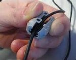
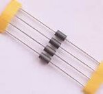
Ive never tried it, but you can maybe checkout ferrite beds.
th.jpg
You probably have seen them like this :
th1.jpg
 

I doubt ferrites will help in this instance. I'm guessing the problem is pick-up from the ignition wiring. When you consider that several KV are pulsed to the spark plugs there will be quite a large electrostatic field in the nearby vicinity. The ideal fix is to use a shielded ignition cable but that may not be possible on your motorcycle because in most cases the cable comes straight out of a moulded ignition coil. A second non-electrical solution would be to build the whole thing in a metal box to screen it from outside interference.

You will have to experiment but this is what I would do:
1. Add 100 Ohm resistors in series with RB4 to RB7 so they can't be shorted together if more than one key is pressed.
2. Increase the pull-up current on RB0 to RB3 by turning off the PORTB intenal pull-ups and instead adding lower value pull-ups externally, I would suggest 2.2K between each of those pins to VDD.
3. If that doesn't fix it, you need a small software change as well, add capacitors of 1nF between RB0 - RB3 and VSS (ground) and add a small delay (~1mS) after driving the row low but before reading the column back.

The idea behind step 3 is that you add a capacitive filter to reduce pick-up on the inputs but as this will slow the fall of the drive signal slightly, you allow a litle longer for it to settle before reading the keypad back. It also gives you some immunity to radio interference from nearby mobile phones which at the moment are also likely to cause you problems.

Brian.
 

Status
Not open for further replies.

Part and Inventory Search

Welcome to EDABoard.com

Sponsor

Back
Top