imranahmed
Advanced Member level 3

- Joined
- Dec 4, 2011
- Messages
- 822
- Helped
- 3
- Reputation
- 6
- Reaction score
- 3
- Trophy points
- 1,298
- Location
- Karachi,Pakistan
- Activity points
- 6,533
Follow along with the video below to see how to install our site as a web app on your home screen.
Note: This feature may not be available in some browsers.

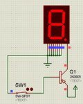
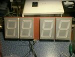
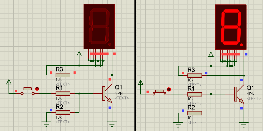
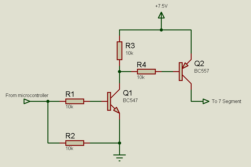
Please check attached circuit,this is not working, what should I do?

Please let me know what is the meaning of this command below.
" if((GPIO & 0x33) != 0x33)" // wait for switch to go low
([COLOR="#FF0000"]GPIO & 0x33[/COLOR]) != 0x33(GPIO & 0x33) [COLOR="#FF0000"]!= 0x33[/COLOR]