Continue to Site

Welcome to EDAboard.com

Welcome to our site! EDAboard.com is an international Electronics Discussion Forum focused on EDA software, circuits, schematics, books, theory, papers, asic, pld, 8051, DSP, Network, RF, Analog Design, PCB, Service Manuals... and a whole lot more! To participate you need to register. Registration is free. Click here to register now.

[SOLVED] PIC Volt Meter and Battery Charging Techniques

Status
Not open for further replies.
There is self discharge of battery which is diffent with individual battery. This is all to keep up with this This can only be estimated by battery voltage. Simbplest is maintaing charge between two levels charger either switched by relay or transistor.Like automatic pump maintains between upper lower and lower level It is good for first stage only.

8_1315053748.jpg


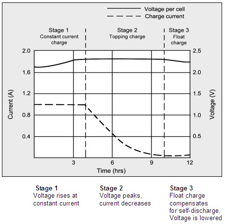
On the other hand there are ics specially made which manage all three recomended stages for battery charging. bq2031 is a popular ic
https://focus.ti.com/lit/ds/symlink/bq2031.pdf
**broken link removed**
It can also implemented in mcu.
If you want complicate things a watthour meter can be constucted for battery discharge using mcu and then charging
in accordance taking care of losses.
 

Attachments

  • pb_battery-charger.pdf
    127.9 KB · Views: 433

Hey Alterlink
I have arranged a pic16F72 from ups kit. As u told its price is 65 rupees so i think it is the cheapest and best pic with lots of i/o pwm interrupts and timers . Only eeprom is missing. Is there any new pic cheap like this and better than this 72?
What is the cheapest PIC18 in pakistan?
 

If I've got it correctly on stock exchange website 1 USD equals 87 PKR. If's that's really the case i must say that PIC micros are much much cheaper in pakistan than in poland, where i live. In my country PIC16F72 costs about 12 PLN (our currency) with 1 USD being equivalent to about 3 PLN. That means that in your country this PIC costs about $0.75 and in my country it costs about $4. That is a huge difference.

Anyway, if the price relations is the same between different micros, then try to look for PIC18F1220. It's price in my country is the same as for PIC16F72
 

18f452,
18f2550, 18f4550 with usb support around Rs500
 
Last edited:


Ok let me explain when the Cutoff term is used in Pakistan.

Charge is terminated when battery voltage reaches the terminal voltage. This Graph is an excellent example. Look at stage 2, voltage is steady, charge can be terminated at any point. What would be the current value? yes it can be any value in stage 2. Do you think the battery is charged? NO....Thats wat i am trying to say. When you hear cutoff tech in Pakistan. they use this type of charging. In every local UPS this method is used plus its unregulated. If a complex method is used then UPS will be expensive.

I am building charger according to this graph. Its a 3 stage battery charger. The voltage is lowered when battery intake current remain less than 200mA and for healthy batteries <100mA. Then voltage is lowered to 13.8V so the battery wont discharge due to environmental conditions such as humidity. Float charging is used when you dont have to use batteries for long time.Else u can cut it off i.e. stop charging as to taking away the terminals(This cutoff is not as used in Pak). but in UPS float charging is required as it is a standby device.
 

That's my personal opinion, but i deeply despise PIC18F2550/4550 because of their silicon bugs.

My master's thesis was build around 18F4550, and I had huge problems with it because of silicon bug, which made SPI virtually useless, and my application relied heavily on SPI. Good thing in all this is that SPI is easy to bit-bang. And another thing is that operating USB inside those chips requires lats of code. In most applications u would just use microchips USB stack made for PICDEM-FSUSB board to connect in generic HID mode because writing your own usb stack is buttload of work
 

KHAN G,Did you mean a chopper(high frequency) transformer based SMPS charger.
see attached file.
 

Attachments

  • SMPS CHARGER.doc
    230 KB · Views: 327

KHAN G,Did you mean a chopper(high frequency) transformer based SMPS charger.
see attached file.

Sorry i dont have time to understand the whole schematic. just cut the main part which is of you interest. and i have never worked with TL494, i prefer do it with basic components.

And to which part you are say "Did you mean". I believe i am the only khan here!
 

khan jee AAP konsa pic use kartay hain. and pakistan main sub say sasta lakin acha pic konsa hay like pic16F72 ? and is main eeprom nahi hay. baqi sub acha hay so eeprom to aaram say external lag sakta hay as alterlink told me its price is just rupees 10 (eeprom) 65(PIC16F72).
Do you have another good pic number available in pakistan whic is cheap than pic16f72 but is better than it?
 

Althoug marked [solved], discussion still going on. Topics changed many times like in chat room(off topic discussion}. It is not an appropriate way. It is annoying for people searching and looking for answer by thread title. Better close and start in new or look for relavent thread to post new query.
 

Sorry i dont have time to understand the whole schematic. just cut the main part which is of you interest. and i have never worked with TL494, i prefer do it with basic components.

And to which part you are say "Did you mean". I believe i am the only khan here!
SAJJAD SAHIB,
In post # 65 at this page you describe,(I am building charger according to this graph. Its a 3 stage battery charger. The voltage is lowered when battery intake current remain less than 200mA and for healthy batteries <100mA. Then voltage is lowered to 13.8V so the battery wont discharge due to environmental conditions such as humidity. Float charging is used when you dont have to use batteries for long time.Else u can cut it off i.e. stop charging as to taking away the terminals(This cutoff is not as used in Pak). but in UPS float charging is required as it is a standby device)----------------
-------------------------------------------------------------------------------
In above paragraphs you mention that you are building a three stage battery charger.
And schematic which i attached here with TL494,its pratical.
The manufacturer of this charger claim that its 3 stage charger.
I am using it since 2 years.
In this circuit we can adjust charging current,and float voltage.
I set 14v and current i ajust is 10amp.
When battery volts reaches at 14v,current become only 100ma.
What basic components you prefer instead of TL494?
 

No No definitely No you are not the only Khan here even khans of remote areas of KPK are here
 

dear friend if u want to remove that duz duz sound then u should have too remove capacitor from ur main transformer then the problem will remove . thanx
 

dear friend if u want to remove that duz duz sound then u should have too remove capacitor from ur main transformer then the problem will remove . thanx
You mean 0.47uf,275v capacitor which is conected with 0 and 260v(inv) loops of main transformer.
 

As i see configuration of circuit, it is a battery charging control circuit.
And charging technique should be as follows.
1=charging current adjustable.
2=Battery level meter,display battery status in percentage(20% 40% 60% 80% and 100% by leds).
3=Charging rate should be divided into 4 stages.
For example if we adjust charging rate 16 amp and batt cut off level is 14.4 volt.
In start circuit will provide 16 amp till battery volts reached at 13.8 v.
At 13.8 volt circuit will change step to 12 amp(75% of adjust charging rate).
Now charging rate has been decreased,battery volts also become low near 13.4v.
At this time during constant 12 amp charging current,battery volts will again increase to 14v.
At 14v circuit will again modify his charging step to 8 amp(50% of adjusted current).
At this stage battery volts also become low. due to less charge rate.
Now at 14.2 volts circuit will change last step at 4 amp(25%) .
This charging mode will remain till bat cut or bat full.
Above mentioned charging rates are constant.
i hope this method is best for battery charging to obtain good specific gravity from battery electrolyte.
In this circuit no need of shunt voltage from negative battery bus bar for adjustment of charge rate .
A ct is used in series of charging loop(140v) of mains transformer.
 

The IC is used PIC16F676. Here is PCB files and HEX code
 

Attachments

  • tracks.pdf
    18.9 KB · Views: 330
  • Trickle CHG 16F676-silk.pdf
    13.2 KB · Views: 334
  • hex.rar
    1.6 KB · Views: 267
dear kg300,
very nice information. pl mentiion which kind of CT is used? if possible post the schematic. thanks
 

Status
Not open for further replies.

Similar threads

Part and Inventory Search

Welcome to EDABoard.com

Sponsor

Back
Top