Okada
Banned
Hi
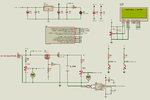
This is the circuit I designed for charging 12V gel and Lead Acid batteries upto 12Ah. Do I have to make any changes to it ?
This is the Solar Panel I am going to use.
**broken link removed**
Circuit Attached.
While designing Inverters I found that Battery Charging current should be 10% of the Battery Ah rating.
For 6 Ah battery can I use 2.5A charging current ? 10% 0f 6 is 600 mA charging current. I don't want the batteries to explode.
Do I actually need the STTH1202 diode for blocking the reverse flow of voltage ? because PWM is used for charging and battery voltage is monitored at all times. If battery is fully charged then PWM duty reduces to 0 and this will turn OFF the mosfet. So all the 21V (open circuit voltage of solar Panel) appear accross mosfet drian and source but as no current flows there will be no heat dissipated in mosfet. Also when battery is fully charged the mosfet will be off and hence there will be no reverse flow of current to panel.
If I use diode then with 2.5A charging current 2.5W power is dissipated in diode. I want to save this power.
FDP8440 Rds(on) is 2.2 mOhms.
- - - Updated - - -
I referred this circuit before designing mine.
https://electronicsforu.com/electronics-projects/hardware-diy/smart-solar-charger
He has one 5E 5W and 1n4007 is series with the battery.
I = V/R = 12V/5 = 2.4A
How does 1N4007 1A diode handle this current ?
He has used 1N4007 as reverse blocking diode but do I need a diode for this purpose in my circuit ?
Attachments
Last edited: