Continue to Site

Welcome to EDAboard.com

Welcome to our site! EDAboard.com is an international Electronics Discussion Forum focused on EDA software, circuits, schematics, books, theory, papers, asic, pld, 8051, DSP, Network, RF, Analog Design, PCB, Service Manuals... and a whole lot more! To participate you need to register. Registration is free. Click here to register now.

PIC microcontrollers... the chip has to be powered independently for programming?

Status
Not open for further replies.

maark6000

Member level 5
Joined
Jan 15, 2013
Messages
92
Helped
1
Reputation
2
Reaction score
1
Trophy points
1,288
Activity points
2,270
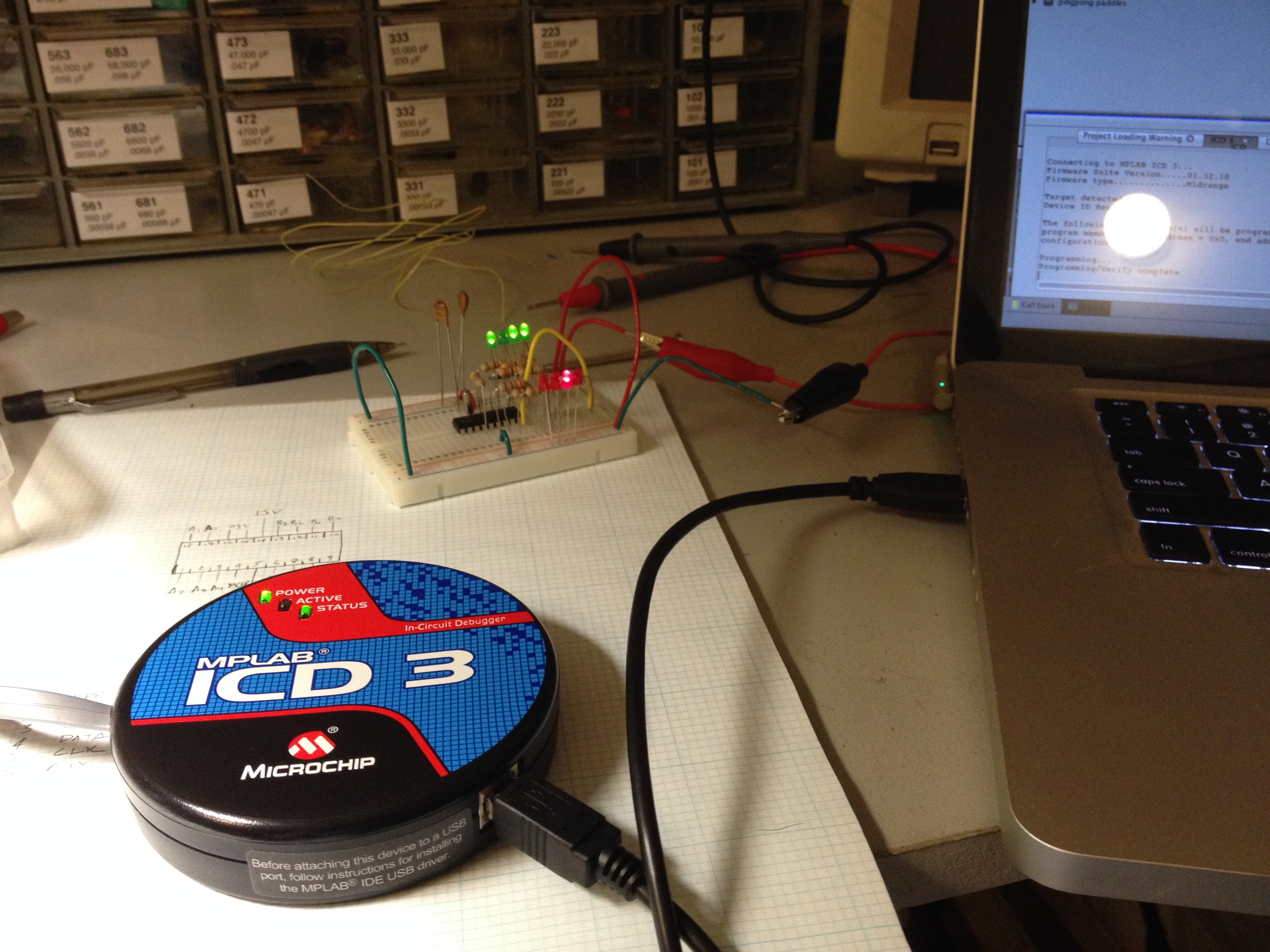
So, I thought I understood this downloading of one's program onto a chip. You plug your programmer (ICD3 in my case) into your USB port on your computer, you connect your target board via the mildly trustworthy RJ-11 cable, insert your chip into the board, and download your program. Since two of the connections from the programmer are Vdd and Vss, the PROGRAMMER will power your chip while downloading / debugging.

But then, that didn't work. MPLAB X kept giving me a "target not found" error, and a little clue was dropped with a dialogue window that opens up and begs "are you sure you're not using a 3.5V chip in there?"

Doing some searching of the internet for the "target not found" error, I found someone respond "the programmer doesn't think the chip has power." Wait a minute. If it's in the programmer... it has power... why else would there be Vdd and Vss pins? But then I thought well, what could it hurt if I try to jam 5 volts into the chip WHILE it's in the programmer... I mean these things are made to work in situ, right? So I did and voila... the program downloaded.

So, my question is... a: did I do that right? and b: am I completely crazy to mistakenly think that the programmer would power the chip while it was in there? and c: I have been reading a book and plenty of microchip documents on programming PIC microcontrollers... why have I never once read "Oh by the way, the chip must be independently powered from some other source than your programmer when you are trying to program it."?

Frustrating.
 

U need to read the document comes with programmer. Any PIC can be programmed through ICD3 without use of external power. So, do check using continuity tester if Vdd and Vss from programmer connect to Vdd and Vss of chip. And also check if other connections are correct according to device datasheet and ICD3 pinouts, bcoz MCU needs to reset through ICD for programming.
U can also power chip from external power supply. But for testing purposes internal supply from ICD3 is enough. Also do note that when MCU is powered from ICD3, u cannot use debug functionality, the debug is option only enabled if using external power supply.
So, there must be something wrong with connections or ICD3 or MCU. But mostly the misconnections. Can u plz share ur schematic? so that exact cause can be found.

Hope that helps.
Ashutosh
 

ICD3 can power the application circuit if it doesn't consume more than 100 mA.

The option has to enabled in programmer setup in MPLAB.
 

"Target not found" could mean a lot of possible issues like a faulty ICD3 hardware, pins shorted to ground on the PIC controller etc..

To program the PIC controller the ICD3 provides the needed power.

ICD3.jpg
 

Thanks for the replies. I will try to find in MPLAB X software what settings may be being used and report back tonight. Good to know that you can only debug with external power! Again, who knew? My ICD3 did not come with any kind of manual... it came with a poster, which perhaps I need to unfold again and reexamine. I thought it came with a manual... it comes with a black folder that was very thick, when I opened it up I found that said thickness was due to a blank notepad! Ha! What a laugh I had at that! Thanks Microchip, I did indeed need a blank notepad... in lieu of even the scantest information on how to use the programmer.

For the record I am using the ICD3 with the ZIF target boards that are made by j1sys. Each board has jumpers to assure that the right info is going to the right pins, and yes... I did have the chip in the correct way as this particular target board is for both 18 and 20 pin devices. I put a voltmeter across Vdd and Vss during one attempt to download the program and it never read anything but 0V.

I'm going to the electronics store today to pick up a RJ-11 cable so I can strip one end to be able to put into a breadboard. I'll have much more control over what is happening with the chip then.
 

Hi,

Bit surprised you cannot run Debug when the target is powered by the ICD3 as Amnandu mentions, can do it ok with a humble Pickit2; though believe the debug on ICD3 is more complex ..

If using extra cables from the ICD3 to your breadboard keep the length as short as practicable otherwise you can loose the high speed programming signals.

Also be aware that if using an external crystal in a breadboard, due to the thin leads on some crystals / caps it can make a poor connection and so loose timing etc.
 
So, a little poking around the internet has led me to a fascinating document called Microchip document 52081A, also known as ICD 3 In-Circuit Debugger User’s Guide For MPLAB X IDE. Hallelujah! And from the good book I will quote section 2.4.3...

Target Powered

In the following descriptions, only three lines are active and relevant to core debugger operation: pins 1 (VPP/MCLR), 5 (PGC) and 4 (PGD). Pins 2 (VDD) and 3 (VSS) are shown on Figure 2-4 for completeness. MPLAB ICD 3 has two configurations for powering the target device: internal debugger and external target power.
The recommended source of power is external and derived from the target application.
In this configuration, target VDD is sensed by the debugger to allow level translation for the target low voltage operation. If the debugger does not sense voltage on its VDD line (pin 2 of the interface connector), it will not allow communication with the target.

Next up... me trying to figure out how to configure the external oscillator, which is required for debugging (???)

Thanks for all your help!!
 

So, a little poking around the internet has led me to a fascinating document called Microchip document 52081A, also known as ICD 3 In-Circuit Debugger User’s Guide For MPLAB X IDE.

So you could simply ask the internet to come to know that your ICD3 has a user manual? Cool.

You didn't yet tell, if the problem was a missing jumper at ZIF adapter or not enabling ICD3 VDD power in MPLAB. As far as I see, the ZIF adapter has all necessary options. A problem for beginners might be, that the documentation doesn't explicitely tell how to set the jumpers for a specific processor, so some reading of processor datasheets and thinking for oneself is required.
 

Ha ha, yes, the internet holds all the answers if you are willing to dig deep enough and are fairly proficient at skimming. Microchip document 52081A is an obscure document however (obviously there are 52,080 documents preceding it), and it is also 91 pages long, so the fact that one must power one's target board in order to program it isn't exactly being made blatantly obvious. The fact that other commenters here (and most likely wiser) were confused as to whether the ICD 3 powers the chip or not speaks to the fact that programming one's chip is in NO way intuitive, and Microchip hasn't exactly done a banner job in pointing out the pitfalls one will make while attempting to do so. I would hate to work in Microchip's help center.

No missing jumper on the ZIF. The problem was simply that I had not powered the chip from an external source. I was never able to find in the IDE where one might "enable" a voltage source internally. But there is so much language about how if you don't power it externally it won't work that I won't ever try to do that. I am currently able to download the program (although in the IDE there is plenty of red print about things failing... however then a dialogue box pops up asking me something about voltages, I click ok, and the end result is program downloaded, program verified).

Interestingly, I still can't get my very simple LED blinking light program to actually operate... so next I will try debugging, however I apparently need to include at least one breakpoint, which I have not yet learned how to do. That will be tomorrow's task. I also plan on making some kind of youtube video of this whole process (assuming I am ever successful) because of the complete dearth of videos showing a program being downloaded onto a chip and seeing it actually work.
 

The fact that other commenters here (and most likely wiser) were confused as to whether the ICD 3 powers the chip or not speaks to the fact that programming one's chip is in NO way intuitive, and Microchip hasn't exactly done a banner job in pointing out the pitfalls one will make while attempting to do so. I would hate to work in Microchip's help center.

No missing jumper on the ZIF. The problem was simply that I had not powered the chip from an external source. I was never able to find in the IDE where one might "enable" a voltage source internally.
Since I'm working with PIC processors (since about 10 years, it's one of the newer processors in my portfolio), I was able to program it intuitively by just browsing MPLAB. This was before MLAB-X. which might have partly lost the intuitive handling. I'm able to avoid it til now.

In classical MPLAB, VDD power is just a programmer respectively debugger option. The conditions for using programmer power asre essentially simple. The programmer must support the voltage of your target chip and the Vdd current must be below a specific limit (100 mA for ICD3).
 

I'm sure older versions of MPLAB were easier to use, the book I am reading on the subject (published eons ago ... 2010) spends about half a page on downloading the code onto the chip, with no mention of target power. I think I and perhaps all of us are predisposed to the EEPROM burner model where you stick the chip in the burner and hit go.

Little bit of a bumpy learning curve with Microchip. But all of you have made it easier, so thank you, and thank you giving me a place to vent. :)
 

I'm sure older versions of MPLAB were easier to use,

Hi,

Assuming you are using a PC and not an Apple, then for the basic chips you are using why not download MPlab IDE v 8.92 and use that instead of X; hopefully it will make smoother running with your ICD3.

I believe you can run both IDE and X on the same system without problems.
**broken link removed**

Various posts about X still show that its has many shortcomings, some seasoned programmers even say they are still so fed up with all its problems / compatability with various compilers they are reverting to IDE until X is fully sorted.
 

I believe you can run both IDE and X on the same system without problems.
That's true, you only need to switch the MPLAB driver between both versions, there's a little program MPDDSwitch32 that does it. MPLAB-X should be used if you want a seamless integrated debugging with the new -X compilers.
 

Well, therein lies the rub. I am using a Mac. My idea was to use it until it got too frustrating, and then try it on my much older (and surely slower) 10 year old XT PC. I just printed out the 91 pages of the manual, going to spend a few days with it... it's a little outdated, some of the commands it asks you to do in the IDE don't exist... but I'm sure I'll be able to get the gist of it and muddle through. I'll keep ya posted. Thanks again.
 

Hi,

Well it might just be worth spending a hour giving IDE V8.92 a go on the XT and see how the ICD3 works / is controlled on that.
When the XT is used for just Mplab doubt you will notice any real speed problems for your early projects.

Think I would have moved to Linux long ago if it was not for most Micro systems being based on Windows only, might be worth getting a cheap second hand windows laptop just for this kind of work ..
 
That is a good suggestion... and I just might take you up on it. I do want to see how far I can go on the Mac before I pull too much hair out. On that front, we're looking good... tonight I wrote a simple program in assembler and downloaded it to the chip, and ran it. See attached picture that it is possible to program in MPLAB X for the mac. ha ha... again, thank you for all your help, I'll be back next week with more questions / heated rants.


Hi,

A very organized desktop, wonder what all those nicely labelled and boxed caps are for, wish my parts were like that :lol:

Assume you programmed it ok with the target self powered or have you found how to power it from the ICD3 ?

Couple of hints might help, looks like a 16F84 chip that you are using with a crystal, as mentioned the thin leads of the crystal and caps can cause problems in the breadboards sockets, its often better to solder the crystal and caps onto a piece of board with 3 thicker leads coming from it to plug into the breadboard.

As you will find there are a lot of chips with inbuilt oscillators that will be fine for most jobs, the 16F88 is a direct equivalent of the 84A but with a lot more features as do the very latest chips like 16F1826/27/47.

As you are starting with assembler, my main language, you might find some of there tutorials of interest.

http://www.winpicprog.co.uk/pic_tutorial.htm
**broken link removed**
http://www.electro-tech-online.com/articles/nigel-goodwins-tutorials-in-c.467/ http://www.amqrp.org/elmer160/lessons/
http://www.epemag.wimborne.co.uk/resources.htm
http://www.mikroe.com/chapters/view/5/chapter-4-timers/
 
awesome! I will check out all those links, I'm really enjoying assembler, it just fires my brain up. I did finally find where one can power the chip from the programmer, it's in one of the many submenus of the configuration window... under "power" i believe. The crystal I'm using is 32.768 kHz, but good idea with soldering the crystal in place. I do plan on moving on to different chips, I have bought some 16F88's, so that may be my next chip. Still getting used to the IDE, I can't get the breakpoints to work, I'm clearly doing something backwards... but I'm going to play with it a little longer before posing what will surely be my next topic... "why can't I get breakpoints to work?" ;)

If you liked my drawers of caps, wait to you see my wall of resistors...


Hi,

Yikes - :shock::grin: wish I could have my resistor pack labelled up like that .


Breakpoints, not sure if you mean IDE X or V8.92 , but in the latter you just right click on the lines you want to have a breakpoint at, though expect X would be virtually the same.

Be aware that different chips have a limit on how many breakpoints you can use.
https://ww1.microchip.com/downloads/en/DeviceDoc/Software%20breakpoints.pdf

Before you get into ICD3 hardware debugging, try the easier software Debugger MPLAB SIM to practice stepping through your code and observing the registers and 'running' to your breakpoints.
 

Attachments

  • 000114.jpg
    000114.jpg
    43.1 KB · Views: 74

Status
Not open for further replies.

Part and Inventory Search

Welcome to EDABoard.com

Sponsor

Back
Top