- Joined
- Jan 22, 2008
- Messages
- 52,487
- Helped
- 14,756
- Reputation
- 29,794
- Reaction score
- 14,122
- Trophy points
- 1,393
- Location
- Bochum, Germany
- Activity points
- 298,376
One wire already lost? Link saysLoad Cell has three wires.
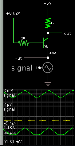
as expectable. Respectively the differential output voltage is centered around half bridge supply.Out-Wire: 4-Wire