Continue to Site

Welcome to EDAboard.com

Welcome to our site! EDAboard.com is an international Electronics Discussion Forum focused on EDA software, circuits, schematics, books, theory, papers, asic, pld, 8051, DSP, Network, RF, Analog Design, PCB, Service Manuals... and a whole lot more! To participate you need to register. Registration is free. Click here to register now.

[PIC] Buck Converter design help needed

Status
Not open for further replies.
Please help me in designing a 15V to 5V buck converter. How should I start ?

Should I calculate the PWM frequency first then duty and then LC filter values ?

or should I calculate LC filter values first and then PWM frequency and duty ?

Please show an example calculations for designing a buck converter. I read the buck converter section in the book Power Electronics by Muhammed H Rashid and understood the equations but I am having problems using them.


synchronous transistor-transistor switchers

Ok. You mean two mosfets right ?

one in series with the +ve bus and another after buck mosfet and parallel to the +ve and -ve bus. Right ?

The parallel mosfet is driven with the same PWM ?


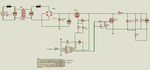
See attached image. Like this ?


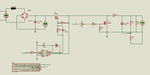
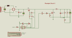
Is the Example Circuit 2 better ? If non Logic Gate Mosfet is used ?
 

Attachments

  • bc1.png
    bc1.png
    33.4 KB · Views: 82
  • bc2.png
    bc2.png
    36.7 KB · Views: 91
Last edited:

I am using IR2184 FET Driver and datasheet tells that HO is in phase with IN and so LO is not in phase that is inverted. So, circuits in previous posts are wrong. Here is my new circuit.

Is this correct.

HO and LO will be complementary. So, can be used in synchronous buck converters where switch 1 and switch works Syncronously.

Common sense tell that switch 1 and switch 2 should not be ON at the same time because then switch 2 will short the +ve bus to GND.

Datasheet of IR2184 is not clear. Unlike other FET drivers it has only one input and two outputs namely HO and LO and I guess they have to be complementary to drive a push-pull circuit.

- - - Updated - - -

By referring the book Power Electronics - Circuits, Devices and Applications, 3rd Ed., by Muhammed H Rashid, page nos. 191 to 193 I have done these calculations for my buck converter.

PWM frequency 20 KHz

Input Voltage to Buck Converter is Vs = 15V

Required Output Voltage is Va = 5V

Load Current is 3A

pk-pk ripple current of Inductor = 0.01A

pk-pk output ripple voltage is choosen as 10 mV

L = 5(12 - 5) / (0.01 * 20000 * 12) = 35 / 2400 = 14.6 mH

15 mH is a standard value and we can use it

So, doing the reverse calculation to find out PWM

f = 5(12 - 5) / (0.01 * 15 * 10^(-3) * 12) = 19444.44 Hz = 19.444 KHz

C = 0.01 / (8 * 0.01 * 19444) = 6.43 uF

we can choose 6.8 uF 16V Electrolytic

doing the calculations again

pk-pk ripple voltage = 0.01 / (8 * 19444 * 6.8 * 10^(-6)) = 9.5 mV

Tpwm = 1/F = (0.01 * 15 * 10^(-3) * 12) / (5 * (12 - 5)) = 0.0018 / 35 = 51.42 us

F = 1/T = 19444.47 same as calculated earlier

Now, how to calculate duty ?

D = Ton / (Ton + Toff)

If I choose 20% duty

then 20% of 255 (pwm duty varied from 0 to 255 in mikroC PWM Library) is 55

55 is the duty value

Ton = 20% of 51.42 us = 10.284 us ON and

Toff = 51.42 us - 10.284 us = 41.136 us


Are these calculations correct ?

So, Can I use 6.8 uF 16V and 15 mH 6A Ferrite Core ?

- - - Updated - - -

Problem is in Inductors. the mH 4A or above Inductors are like transformer package.

If I choose uH inductors then f becomes MHz.

What to do ?

- - - Updated - - -

This is the new calculation I did. It is correct and only good for Proteus simulation.

Input Voltage to Buck Converter is Vs = 15V

Required Output Voltage is Va = 5V

Load Current is 3A

pk-pk ripple current of Inductor = 0.01A

pk-pk output ripple voltage is choosen as 10 mV

L = 5(15 - 5) / (0.01 * 20000 * 15) = 35 / 2400 = 14.6 mH

15 mH is a standard value and we can use it

So, doing the reverse calculation to find out PWM frequency

f = 5(15 - 5) / (0.01 * 15 * 10^(-3) * 15) = 22222.22 Hz = 22.22 KHz

C = 0.01 / (8 * 0.01 * 22222) = 5.625 uF

we can choose 5.6 uF 16V Electrolytic

doing the calculations again

pk-pk ripple voltage = 0.01 / (8 * 19444 * 5.6 * 10^(-6)) = 10.044 mV

//Tpwm = 1/F = (0.01 * 15 * 10^(-3) * 15) / (5 * (12 - 5)) = 0.0018 / 35 = 51.42 us

//F = 1/T = 19444.47 same as calculated earlier

Tpwm = 1/F = 1/22222 = 45 us

20% duty means 0.2 * 255 (duty value is between 0 and 255 in mikroC PWM library)

duty value = 51

20% of 45 us = 9 us

Ton = 9 us

and

Toff = 45 us - 9 us = 36 us

D = Ton/(Ton + Toff) = 9 us / 45 us = 0.2 = 20%
 

Attachments

  • bc3.png
    bc3.png
    39.2 KB · Views: 94
Last edited:

Gate driver circuit finally working. IR2184 does explain the signal polarities, see e.g. figure 1.

A typical buck inductor dimensioning if for Iripple equal to 30% of rated current, not 0.3 %.
 
  • Like
Reactions: Okada

    Okada

    Points: 2
    Helpful Answer Positive Rating
Gate driver circuit finally working. IR2184 does explain the signal polarities, see e.g. figure 1.

Where is figure 1 ?

Hi, Thank you FvM.

Saw the figure 1 on page 6 of IR2184 datasheet. They are complementary.
 

Buck Converter is not working in Proteus.

These are my calculations. Project attached.

Vs = 15.4V
Va = 5V
Output Current = 2A

delta Vc = 20 mV

delta I = 0.6A

L = 100 uH 4A choosen

f = 5(15.4 - 5) / (0.6 * 100 * 10^(-6) * 15.4)

= 56277 Hz = 56.277 KHz

C = 0.6 / (8 * 56277 * 20 * 10^(-3))

= 66.63 uF

68 uF choosen

T = 1/F = 1/56277 = 17.8 us

If 30% duty then

30% of 255 = 76.5 = 77 is the pwm duty value
 

Attachments

  • Buck Converter.rar
    71.9 KB · Views: 84

to Stay in safe side follow this instruction:
1-destroy your current design and start from zero (proteus for simulation only ... not for real life)
2-select your requirements of power, voltage and ampere
3-select best or suitable topology for your design
4-select power devices of your project (Ferrite core size, Frequency, mos transistor, ....)
5-select control and feedback for your design
6-Start now
 

The problem is solved. I made changes to the circuit and re-calculated component values and now circuit design is complete. I have ordered the components and waiting for it. I will get the components in 3 or 4 days. I will build the circuit and update this thread about what happens in the hardware.
 
The problem is solved. I made changes to the circuit and re-calculated component values and now circuit design is complete. I have ordered the components and waiting for it. I will get the components in 3 or 4 days. I will build the circuit and update this thread about what happens in the hardware.

Great job
i advice you to read more and more about switching mode power supply
it's full of secrets and not easy at all to apply.
 
Last edited by a moderator:
  • Like
Reactions: Okada

    Okada

    Points: 2
    Helpful Answer Positive Rating
Yes badea. I have read DC-DC Converters chapter of the book Power Electronics by Muhammed H Rashid. I am now reading application notes by different component manufacturers like TI, Fairchild, On, ST, etc... The application notes are more practical. If my buck converter works fine on hardware then I will build more converters for different voltages.
 

Status
Not open for further replies.

Similar threads

Part and Inventory Search

Welcome to EDABoard.com

Sponsor

Back
Top