Continue to Site

Welcome to EDAboard.com

Welcome to our site! EDAboard.com is an international Electronics Discussion Forum focused on EDA software, circuits, schematics, books, theory, papers, asic, pld, 8051, DSP, Network, RF, Analog Design, PCB, Service Manuals... and a whole lot more! To participate you need to register. Registration is free. Click here to register now.

PIC based voltmeter for 16f877

Status
Not open for further replies.

paramesium

Newbie level 5
Joined
May 16, 2011
Messages
8
Helped
0
Reputation
0
Reaction score
0
Trophy points
1,281
Activity points
1,346
Hello, i have read some of the threads about pic based voltmeter.
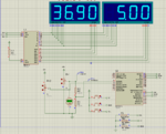
If i am measuring an external voltage source by using PIC, where should i ground the external source(since the positive side is on RA0) ? together with the PIC gnd? Please kindly guide me, thanks!
 

Basicily you just connect the positve through a resistor divider has the pic can only handle 0-5V any thing more would result in damaging the pic and the negative to common GND, The same GND has the pic is connected to hope this clears it up for you
 

Here's a PIC Voltmeter Project showing the connections you are referring to:

circuit.GIF


3 Digit PIC Digital Voltmeter

Hope the info comes in handy.

Ciao
 

Well I guess that gives you an opportunity to improve on someone elses design. The original intent of posting the schematic was to help paramesium connect his voltmeter's inputs correctly.

What exactly is wrong with the code? The zip file includes the C source file, just make the appropriate modifications and recompile.

If you really need another PIC voltmeter project, let me know I have several bookmarked.
 

This is my own vesrion. There is a bit more to it than just a standard meter is uses a MAX7219 chip and a 16F876 but use any pic. It reads 0-50V and 0-10amps, It be be a daul amp or voltage meter. Some where I have a big font GLCD meter also a wireless meter that uses RF this version is work in progress all working but in the proccess of trying a 18bit A/D converter.
 

Attachments

  • MAX7219.PNG
    MAX7219.PNG
    106.6 KB · Views: 163

Have you incorporated any of Microchips digital potentiometer in your designs?

I just received various samples from Microchip, they are very interesting. A multirange voltmeter maybe a perfect application.

Microchip Digital Pot MCP4017
 
Have you incorporated any of Microchips digital potentiometer in your designs?

I just received various samples from Microchip, they are very interesting. A multirange voltmeter maybe a perfect application.

Microchip Digital Pot MCP4017

What would you use the digital pot for in a voltmeter , If I'm correct they only have a max working voltage of VDD on the wiper. I've used the AD8402 digital pot which is SPI version ans 256 steps
 

You are correct, so much for that idea.

How did the AD8402 perform and what was the application?
 

you could use a 4066 to switch in different values of resistors to make an auto ranging meter but this would only be to compensate for the slight differnce in the voltage readings. becuase I found over the range of voltage tou can either get it spot on at the lower end or higher end acording to my fluke meter. I might have ago at trying it only because I'm a perfectionist and like it to be the best.
The application for the digital pot was to control a power supply with a 0-5V input. It worked ok out found it was accurate enough on setting the ouput voltge so i ditched the idea. this may have been an hardware issue thow on the power supply and not the digital pot

The above meter I've used in the velleamn 0-30V 0-10A power supply which replaced the orginal led panel meter because there design was jumping around a lot tried lots of things to cure but never did so I did my own
 

What would you use the digital pot for in a voltmeter , If I'm correct they only have a max working voltage of VDD on the wiper.

I guess that might explain why looking back over Microchip's pages on their digital pots, I saw so very few appnotes. Great idea, but limited practicality.

Oh well, they're all freebies, I find some good use for them, programmable filter maybe.

I might have ago at trying it only because I'm a perfectionist and like it to be the best.

I resemble that remark! Sometimes I have to stop myself and say, "Enough is Enought!"

Sort of like that never ending project.
 
I know that feeling the never ending project :grin:
you may find a use for the digtial pot I have a few in my junk box might find a use for them one day.
Here are some more pic's of another meter using a nokia GLCD display I was playing with but not got around to finishing it:grin:
 

Attachments

  • meter1.JPG
    meter1.JPG
    109.8 KB · Views: 130
  • meter2.JPG
    meter2.JPG
    109.7 KB · Views: 120
  • meter3.JPG
    meter3.JPG
    107.4 KB · Views: 111

Nice.

What's your coding language of preference? Are you just PICs or do you ever use other lines of MCUs?
 

Nice.

What's your coding language of preference? Are you just PICs or do you ever use other lines of MCUs?
I use PDS and only use pic's, PDS is powerfull and easy to use/understand
 

ok, thanks wizpic and bigdogguru for very useful information :cool:
 

ok, thanks wizpic and bigdogguru for very useful information :cool:
What's your set up like what vlotage do you want to read and what's the connections to your pic and I'll write your some code and upload the hex, I'm having fun palying
 

i am actually doing some solar panel charging on a battery. when i press a button, the solar panel will be an open circuit, and i will be measuring the charging level of the battery using PIC. the voltage range for the battery should be 0 - 2.5V.
(P/S: the circuit will be using voltage regulator and suitable resistance to generate proper current)
 

This is my own vesrion. There is a bit more to it than just a standard meter is uses a MAX7219 chip and a 16F876 but use any pic. It reads 0-50V and 0-10amps, It be be a daul amp or voltage meter. Some where I have a big font GLCD meter also a wireless meter that uses RF this version is work in progress all working but in the proccess of trying a 18bit A/D converter.

Hi wizpic, i must admit this is is a great project of yours, i was wondering is it posible from you to post a C code for pic 16F876, since recently i have built a power supply my selfe ( 0-30 volt and 0-5 amps) im intend to use this project as an panel meters,
P.S i was wondering is it posible to use for digits for ammeter to so it will get more accurate decimal points of miliamps ( 5.000 )
regards

Sorry I don't use C only PDS and yes it the decimal can be moved quite easy
 

ok wizpic can you post more detailed schematic and PDS for this project of yours?
thanxMAX7219.PNG
 

Status
Not open for further replies.

Similar threads

Part and Inventory Search

Welcome to EDABoard.com

Sponsor

Back
Top