Continue to Site

Welcome to EDAboard.com

Welcome to our site! EDAboard.com is an international Electronics Discussion Forum focused on EDA software, circuits, schematics, books, theory, papers, asic, pld, 8051, DSP, Network, RF, Analog Design, PCB, Service Manuals... and a whole lot more! To participate you need to register. Registration is free. Click here to register now.

[SOLVED] Pic 16f876a Pure Sinewave inverter

Status
Not open for further replies.
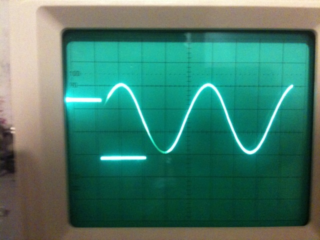
A/B should be 50Hz and also duty cicle should be 50%. From jour picture is not so clear about duty cicle. Could you repeat osciloscop test for A/B signal.
Use (for now) only hex withot a/b check.
 

A/B and output must be synchronous, i.e positive output voltage (and high current, curr-h) when A/B=5V (logic 1) and negative when A/B=0V (logic 0)
 

its 50% but its not showing in the picture i just switched the output now the signal is great as u can see in the attachment but the voltage drops 230v to 221 with a 50w lamp
 
Last edited:

If voltage droped down with load, somehing is wrong with current sensing. Check connection of the current transformer, remember what is written about phase of these signals, or feedback from current transformer is to weak to keep constant voltage with increasing load.

Curent transformer ratio should be like 1 : 1000, in my case I have 2 turns on primar (d=1mm) and 2000 turns on secondar (as tiny as possible)
 

i have no idea whats my current transformer :S and where i am we canot buy a current transformer as we wish so can u tell me what is the voltage on the transformer when a 50w light bulb is on?? so i can adjust the trans
 

I made it by myself. Without transformer there is no chance to have correct voltage on output with diferent load. So take ona old small transformer, remove iron away, remove cu wires and simply put 2 turns of 1mm diameter for primar and separated 2000 turns for secondar and that should be enough. Next step is checking phase of current signal and that's all.
 

ok ill try that at work cause i have no cu wires here at home so tomorow ill try it and ill come back to u thanx again Mr. ccaliforniajoe

---------- Post added at 21:51 ---------- Previous post was at 21:50 ----------

btw is it possible not to include the current check in the software???
 

In case not including it you will have voltage drop with increasing load.
 

current check closely monitor output current amplitude and shape, so if you remove it, definately some other problems will rise
 

hello guys i bought 3 current transformers today and i tried them all and i even built one as california said 1000/2 turns still no change :S
 

Hm, you should read carefully: 2/2000 turns, check phase of the signal - it is very important, also check phase of V_OUT signal, it is also very important.
Ones again, check with osciloscop signals: A/B, Curr_h and V_OUT! All those signals MUST be in phase, which means: when A/B is positive also Curr_h and V_OUT should be positive and on the other side when A/B=0, Curr_h and V_OUT should be very close to 0V.
I hope, this is clear enough.
 

curr_h V_out and A/B are in phase thats first second i wrote in the previous post wrong its 2000/2 and still nothing is changing
 

check these videos out cz im feed up of the same answers one is vout vs A/B the other is cur_l vs Vout
 

Attachments

  • mov.rar
    306.8 KB · Views: 439

It looks ok to me.
So the only problem is voltage drop from 230v to 221 with a 50w lamp.
I suggest next step: connect voltmeter negative to GND and positive to +U (as close as possible to Q1, Q2, Q3, Q4) and do meassuring first without load and second with load. Post here both of the results.

Also connect osciloscop parallel to voltmeter for both cases, set input for AC and put range of input voltage as low as possible, then do some pictures.


as u can see :S the 12V dc contains a shitty AC signal but i cant explain y ?? my pcb in the other pic u can see it the traces are wide and the 2 capacitors are 27000UF each
 

Please follow the instructions on post 777. Do meassuring without load first and second with load then post results and pictures here.

Regards
 

this is without load and with load its the same with higher amplitude
 

I think, construction of your PCB is not well desighned. Why did you change original design? For example, my desighn doesn't have this problem.
 
for one simple reason because this design is used in professional invertors
anyways ill try to see how i can remove this problem and ill get to u soon
 

Hello! Tell me how to alter the scheme so that instead of 12V input voltage was 72V. thank you
 

Status
Not open for further replies.

Part and Inventory Search

Welcome to EDABoard.com

Sponsor

Back
Top