AbhimanyuSingh
Member level 1
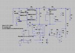
I am attaching the image as well as the .zip file of my ltspice circuit. The image file of the circuit could be very confusing. The problem I am facing here is with the PI controller at the output of the converter. The output voltage is supposed to be around 37 volts, which it is and hence the voltage across R3 is around 2 volts, or a little less than that. But the voltage at the non-inverting pin of the U2 remains in microvolt as current flows and voltage drops down across R8. The value of R8, R4 and C3 were calculated based upon the compensation needed theoretically. But the voltage at the inverting pin of U2 is very very low, in microvolts and the output of the U2 is very high around 200KV. and the rest of the circuit behaves insanely. The output of U2 is vco, which is used further in the multiplier, B1. What stupidity have I done here with the PI controller? Or anywhere else.