R
RitchRock
Guest

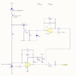
Hi all, I'm working on an optical sensor and am looking to increase my SNR. I've constructed a circuit to cancel out LED emitter noise with feedback control. PDref monitors just the emitter, while PDsig carries the sensor signal + emitter noise. Feedback consists of integrator -> JFET VCR -> current divider. Please see attached circuit. LT Spice simulation works well, but in real-world implementation I don't see the JFET resistance changing (I believe it should balance when I move VR1). Any suggestions on what I could be missing from moving from the simulation to prototype?


Last edited by a moderator: