Continue to Site

Welcome to EDAboard.com

Welcome to our site! EDAboard.com is an international Electronics Discussion Forum focused on EDA software, circuits, schematics, books, theory, papers, asic, pld, 8051, DSP, Network, RF, Analog Design, PCB, Service Manuals... and a whole lot more! To participate you need to register. Registration is free. Click here to register now.

[SOLVED] phase correction - RF experts I need your help please!

Status
Not open for further replies.
S

slow_rider

Guest
Hello All,

I'm building an impedance box to test an amplifier (box with resistors that can be switched in series and out of the circuit to represent different impedances between the input and output terminals). Resistors are from 15 Ohm up to 200 Ohm.

The resistors that are being used are Arcol NHS100 type which are pure resistors, tested with our impedance analyzer from 100KHz to 2MHz. Our amplifier is working at 500KHz and outputs up to 50W on various impedances.

The input & output to this box is a standard coax cable, however only the inner conductor is used and the shield is connected to the box shield to prevent crosstalk between channels, however there is no "return current" on this outer conductor so the cable is acting like a coil and adds about 40 degrees phase shift which is easily correctable using a proper capacitor.

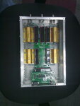
As you can see in the picture, the resistors are set around the PCB that houses a small controller IC and reed relays to switch the resistors in and out of the circuit. When I switch a resistor in (especially the larger ones, 100 and 200 Ohms) they also seem to be coils adding up to 20 degrees phase shift. I wish I could say the "coil effect" each one has is additive, however it is not. So I can not simply match each resistor with a small capacitor is series and solve the problem.

Another thing that is interesting to note is that this exact same circuit with the same PCB housed inside a plastic box does not suffer from these effects (almost at all). This is the very first project I am doing with RF and have no experience. So if anyone could direct me to a solution I will greatly appreciate it.
 

Attachments

  • 14032011332.jpg
    14032011332.jpg
    430.9 KB · Views: 104

Outer coax conductor is also used. It carries same current as inner conductor but with opposite direction. If no current in outer conductor=> no current is possible in single inner conductor. That is a bit the main idea with using a coaxial cable.
Do not believe that cable act as a coil but it can add signal delay. A 40 degree cable delay at 500 kHz corresponds to something 10 meters. How long are your cables?
Do not think it is a such big coil-effect that you see for the resistors, as its inductance is rather low at 500 kHz but is so, is it easy compensated for a certain frequency with a capacitor.
Some of the problem you are seeing are probably because of less good matched impedance, resulting in high ground current.
A plastic box can hide some effects due to these ground currents as a kind of isolator but guess that VSWR at TX out is rather high then.

A easy way to detect reflecting and unwanted outer shield current is to wind a coil, 10-20 turns, any unshielded wire, around your coaxial cable and connect to a oscilloscope.
 

Just to clarify, the input BNC sees signal only on the inner (main) conductor, from there is goes through the resistors in the box, from there to the output BNC connector (also to the middle conductor). The coax shield is simply hooked to the box to act as a shield from crosstalk between a few different channels. The coax length is 3m. You would have to trust me that this is the way the system is hooked up - which is not a standard use of the coax cables. The coax has inductance and capacitance cancel each other, so the wire is the coil and the capacitance with the outer shield is the capacitor - if it has the "return"current. in my case it does not. this is why a capacitor it used to cancel out the inductance of the cable.

Another thing, there is no point in matching the cables for 50 Ohms since the resistors are in many values other than 50 Ohms, so there will be returning waves and such anyway, this is known the amplifier is planned to deal with this problem. However as a result of this specific mismatch in the cable the phase shift is caused which makes the amp see impedance which is not 100% real but also reactive.

The cable part is solved with a capacitor (around 7.5nF BTW), but what could cause the same effect, being not additive, with the resistors?
 

So input BNC sees signal on the inner conductor, from there is goes through the resistors in the box, from there to the output BNC connector, and there is no return current?
According to any physical law will no effect be transferred either.
It is RF, yes, but it basically works as any torchlight circuit. No return current=> no light possible.
 

The resistor box input sees the signal from the amplifier output and the output from the resistor box goes into the amplifier return so the circuit is complete...
 

You would have to trust me that this is the way the system is hooked up.
The problem is, that your description of the setup is still unclear. And I'm only willing to ignore possible return currents through the cable shield, if you tell, that it's unconnected at the other cable end. Is it so? If the cable shield however forms a closed loop, it will affect impedances.

I would generally prefer to see a schematic, that clarifies how you are measuring phase for the overall setup. If it includes all existing ground and cable shield connections, we don't need to rely on belief.
 

I've attached a schematic that shows the hookup of the system. The amplifier output goes into the middle conductor of a BNC connector. I hook a 1.5 - 2m cable to that BNC and the other end goes to the resistor box input BNC. The input from the main conductor goes through the resistors (or the bypass relays) and into the output, from there back into the amplifier to close the loop. The shield of the cable is shorted with the metal box housing the resistors at one end. The other end is connected to a split box that takes the amplifier's output and allows to connect BNC cables. The BNC connector on that box is metal and so is the box, however it is not connected to earth ground or any other ground, not even to the amplifier. So as far as I can see it can be seen as unconnected at that end. The resistor box housing is connected to ground. The amplifier is floating. I hope that this is a good description.
 

Attachments

  • 1.bmp
    753.7 KB · Views: 73

If the amplifier is floating and not connected to ground, direct or indirect, will your coax cables external shields interconnection cause a good signal path for signals between the both inner conductors.
 

If the amplifier is floating and not connected to ground, direct or indirect, will your coax cables external shields interconnection cause a good signal path for signals between the both inner conductors.

Even though they are connected to ground? As far as I know this should stop any RF from leaking out of the cables since ground earth is at a constant known voltage potential?
 

Ground is a relative reference. If whole circuit is floating does ground relative potential not affect any internal potentials differences.
 

The other end is connected to a split box that takes the amplifier's output and allows to connect BNC cables.

The below schematic shows my understanding of the shield connection. So you have in fact a closed loop. It's changing the loop inductance measured over inner conductor.


Regarding the connection of the shields at the junction box (amplifier side). I can change the BNC to plastic housing that would open the circuit. Do you think that would do for this specific problem?


Here is a more accurate schematic of the setup, although I don't think it has more information which is needed.

1.jpg

The main cause for the post were not the cables. Inserting the capacitor at the input of the resistor box solved the phase from the cables. The reason for the post is the inductance increase as I insert different resistors into the circuit. When they are all bypassed the total phase shift of the box + cables reads almost the same as the cables themselves so I know the box is not changing anything when everything is bypassed. However when I insert the different resistors I can see changes.

The same circuit works OK with almost no inductance added when housed in a plastic box and banana cables used for both input and output. The question is, what have changed that causes this? This is my main concern here...
 
Last edited:

The closed loop will almost cancel the conductor inductance contributed by the loop marked below. If you say, you are compensating the loop inductance of each setup, if won't matter at first order. But because the inductance has also skin effect losses, the exact behaviour is more complex.

Another effect of the metal housing is connecting the shield capacitance of the coax cable, which is floating in case of a plastic housing. Although you say the amplifier is "floating", I would expect a finite common mode impedance though. So the shield ground connection will most likely matter somehow.

Your observation, that the error is increasing with higher load resistance would also suggest a apacitance effect. Depending on how you measure the load impedance, the effect of the capcitance may be different. For an detailed analysis, the complete equivalent circuit of the generator output measurement would be required. If we estimate the cable capacitance effect for a simple RC parallel cicrcuit, we get 20° phase shift with 200 ohm and 600 pF, coresponding to 6 m of coax cable.


    V

    Points: 2
    Helpful Answer Positive Rating
"the input and output terminals" if they both actually are output in a balanced TX output, then I can understand that it at least to a certain degree is a closed loop. Coupling effects due to half floating shields and half floating enclosure seems a bit undefined and due to this is it likely that high resistive values as load on a balanced output increase your vector impedance uncertainty.
 

The closed loop will almost cancel the conductor inductance contributed by the loop marked below. If you say, you are compensating the loop inductance of each setup, if won't matter at first order. But because the inductance has also skin effect losses, the exact behaviour is more complex.

Another effect of the metal housing is connecting the shield capacitance of the coax cable, which is floating in case of a plastic housing. Although you say the amplifier is "floating", I would expect a finite common mode impedance though. So the shield ground connection will most likely matter somehow.

Your observation, that the error is increasing with higher load resistance would also suggest a apacitance effect. Depending on how you measure the load impedance, the effect of the capcitance may be different. For an detailed analysis, the complete equivalent circuit of the generator output measurement would be required. If we estimate the cable capacitance effect for a simple RC parallel cicrcuit, we get 20° phase shift with 200 ohm and 600 pF, coresponding to 6 m of coax cable.


So what if I disconnect the coax cable shield from the resistor-box case? Will that help?

---------- Post added at 23:33 ---------- Previous post was at 21:59 ----------

"the input and output terminals" if they both actually are output in a balanced TX output, then I can understand that it at least to a certain degree is a closed loop. Coupling effects due to half floating shields and half floating enclosure seems a bit undefined and due to this is it likely that high resistive values as load on a balanced output increase your vector impedance uncertainty.

So what would you suggest to solve this problem? Based on the current setup (without rebuilding anything)?
 

I know to little about this circuit to say anything definitive. My general opinion is that ground should be well defined and with low ground losses between all different parts of the measurement setup ground. Weak or broken ground is evil. When loading transmitters, mainly for wide band impedance optimizing, do I not worry much about timing delay caused by cables or PCB traces as long as it exist a plane which I can define in a particular measurement setup as t=0. At that place on PCB must RF ground be as stable as possible to be able to do correct measurements as I am probing relative this ground. If the transmitter is balanced does it in most cases still have a reference to ground via Vcc ground, RF grounded filters and such so it had not been any problem yet.
If you have seen differences in phase between metallic and plastic enclosure, measured relative a reliable phase reference point, then I guess that the metallic part somehow becomes a part of the circuit in a poor defined ground loop. If a coaxial cable shield is connected to this ground loop or not, is just a selection between two different problems.
 
  • Like
Reactions: FvM

    FvM

    Points: 2
    Helpful Answer Positive Rating
So what if I disconnect the coax cable shield from the resistor-box case? Will that help?
It would open the loop.

I agree with E.Kafeman, that the unknown ground impedance of the "floating" generator is a basic problem. Also a possible inbalance can affect the results. Furthermore it's unknown, how the common mode load impedance affects your impedance measurement.
 

Status
Not open for further replies.

Similar threads

Part and Inventory Search

Welcome to EDABoard.com

Sponsor

Back
Top