cupoftea
Advanced Member level 6

Hi,
Do you agree, the PFC inductor in the following App Note (pg17) has been designed totally in error? They have violated the datasheet. It’s a 2 stacked 77083A7 torroid(s) from Mag-Inc. They wound it with 64 turns.
PFC App Note:
The PFC is 2500W from 230VAC input. Therefore, peak inductor current will be in excess of 15.3A.
However, 64 turns x 15.3A = 979.2
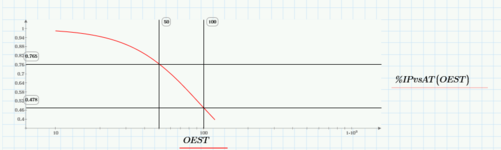
The 77083A7 torroid datasheet clearly only permits Ampere.Turns up to 800.
This is a clear violation of datasheet. Presumably they just assumed the “AL VS NI” graph continued as a straight line after NI=800? They are totally in error in making this assumption?
77083A7 datasheet:
Do you agree, the PFC inductor in the following App Note (pg17) has been designed totally in error? They have violated the datasheet. It’s a 2 stacked 77083A7 torroid(s) from Mag-Inc. They wound it with 64 turns.
PFC App Note:
The PFC is 2500W from 230VAC input. Therefore, peak inductor current will be in excess of 15.3A.
However, 64 turns x 15.3A = 979.2
The 77083A7 torroid datasheet clearly only permits Ampere.Turns up to 800.
This is a clear violation of datasheet. Presumably they just assumed the “AL VS NI” graph continued as a straight line after NI=800? They are totally in error in making this assumption?
77083A7 datasheet: