Continue to Site

Welcome to EDAboard.com

Welcome to our site! EDAboard.com is an international Electronics Discussion Forum focused on EDA software, circuits, schematics, books, theory, papers, asic, pld, 8051, DSP, Network, RF, Analog Design, PCB, Service Manuals... and a whole lot more! To participate you need to register. Registration is free. Click here to register now.

permittivity impact on Axial Riato

Status
Not open for further replies.

rf1008

Full Member level 2
Joined
Mar 30, 2012
Messages
129
Helped
7
Reputation
14
Reaction score
7
Trophy points
1,298
Activity points
2,219
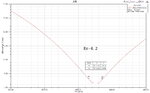
I simulated UHF patch antenna with circular polarization in HFSS, and found the permittivity impact on AR is very large. e.g. when er=4.0,AR is 1.5, when changed er to 4.2, AR is 10.

It's too much variation although i chould fine tune the model to improve the AR.


Is my conclusion right ? thanks!

BTW: FR4 sub and single input with back feed.
 

Probably you are using a design without a power splitter with 90 degreed delay in one of the paths.

The single feed circular patches make use of slight detuning between the orthogonal resonances. One resonance is 45 degrees in advance and the other is 45 degrees behind resulting in overal 90 degrees phase shift (inductive or capacitive behavior). However changes in the resonance frequencies due to change in er will result in different phase shift in both resonances, hence in poor axial ratio.
 
Last edited:

Yes, I use only one feed port without a power splitter with 90 degreed delay in one of the paths.

I've never designed antenna before and tried to simulated it recently, and found it's difficult to meet the AR for single feed patch on FR4.
 

Attached are three AR curves with Re=4.0,4.2 and 4.4,in which the AR varied very much.
It's difficult to control the permittivity of substrate to be in very small variation. Is there any methods or anything wrong here? thanks a lot!

AR_er4.0.JPGAR_er4.4.JPG
 

Attachments

  • AR_er4.2.jpg
    AR_er4.2.jpg
    103.6 KB · Views: 80

Attached are three AR curves with Re=4.0,4.2 and 4.4,in which the AR varied very much.
It's difficult to control the permittivity of substrate to be in very small variation. Is there any methods or anything wrong here? thanks a lot!

View attachment 78674View attachment 78675

Seems like you have simulated 3 times just changing the di-electric constant, keeping the antenna dimensions constant. You should also consider that by changing the di-electric constant, your patch size tends to change for a certain fixed frequency. Please re-design your antenna with new di-electric constant and then you will notice that there is no big difference in AR.

Note: size of antenna is proportional to Effective Di-electric Constant or rather Di-electric constant of antenna. !
 

I think this antenna is very narrow band also (VSWR=2). If you don't have control over Er, and you need good AR, you can't use this antenna design. You will get better AR versus frequency by using a 2-feed patch (via splitter).

You may also check the radiation efficiency or gain (you need the diectric loss factor of your FR4 material). If it is below expected, you need to increase the distance between the patch and the ground plane. That means thicker substrate or a seperate ground plane that is seperated from the PCB material (so there is air inbetween).
 

Seems like you have simulated 3 times just changing the di-electric constant, keeping the antenna dimensions constant.

What rf1008 did makes perfect sense. The permittivity of FR4 has large tolerances and the exact value is not known in advance. The antenna performance should be checked over the range of expected permittivity values.
 

What rf1008 did makes perfect sense. The permittivity of FR4 has large tolerances and the exact value is not known in advance. The antenna performance should be checked over the range of expected permittivity values.

or rather test the substrate for permittivity and design your antenna accordingly.

By changing the di-electric on simulation and wondering about the results (the freq shift in rf1008's case), you will head nowhere.
 

vedagarbhamsandeep, I don't agree.

If you have designed with FR4, and measured it, you will notice a wide spread of permittivity. There is no quality control on permittivity for this material, so even if you measure it, you will get something different with the next batch.

Changing the permittivity on simulation, to check the sensitivity/yield and estimate worst case performance, is very important if you use the "bad" FR4 material.
 

so how would you plan a production on FR4 ?

For the products that I designed for FR4, I did exactly what rf1008 did: analyze the results/yield for the expected range of permittivity (in my case from measurements over different batches), and center the design parameter for this spread in permittivity. And if the tolerances and loss of FR4 are not acceptable, then use another material. Or in case of the antenna, if it really has to be FR4, another antenna type might be considered that is less sensitive to the permittivity.
 

Don't you think there is a big loss of time and money when you develop different versions on different substrate batches and repeatability is not achieved end of the day.

Anyways, which antenna types do you think are less sensitive to permittivity ?

I feel regardless of antenna type, the main issue lies with the substrate itself.
 

Don't you think there is a big loss of time and money when you develop different versions on different substrate batches and repeatability is not achieved end of the day.

Of course, nobody wants to design multiple layout version. You missed the point.

Anyways, which antenna types do you think are less sensitive to permittivity ?

For PCB integrated antennas, how about PIFA (ground cutout near radiator => only small percentage of the field in PCB => less sensitive to substrate properties)? Not directional, so this is not a patch antenna replacement, but it is less sensitive to substrate permittivity and also less troubled by the substrate losses. The higher gain of the patch antenna is somewhat reduced by high FR4 losses, so that the effective difference in gain isn't that much.

But let's not highjack this thread ... the original question was about axial ratio, so rf1008 has specific requirements for his antenna.
 
Last edited:

Hi all, thanks!

I really just want to verify the impact of permittivity of FR4 on patch antenna design because i have no the related experience.Above observation is just based on simulation.
My first requirement is to get double check and confirmation from you all. and the second one is that how to improve the bad performance on FR4.

- - - Updated - - -

And even,i doubt the tolerance of permittivity of other "good" substrate for instance Rogers' sub between different date codes.
 

And even,i doubt the tolerance of permittivity of other "good" substrate for instance Rogers' sub between different date codes.

No reason to doubt that - for these "RF" materials, there are defined tolerances for permittivity, and quality control where the values are checked.
 

Status
Not open for further replies.

Part and Inventory Search

Welcome to EDABoard.com

Sponsor

Back
Top