Continue to Site

Welcome to EDAboard.com

Welcome to our site! EDAboard.com is an international Electronics Discussion Forum focused on EDA software, circuits, schematics, books, theory, papers, asic, pld, 8051, DSP, Network, RF, Analog Design, PCB, Service Manuals... and a whole lot more! To participate you need to register. Registration is free. Click here to register now.

Perfect ground with finite dimension in 4NEC2

Status
Not open for further replies.

kakar133

Member level 2
Joined
Sep 16, 2010
Messages
49
Helped
0
Reputation
0
Reaction score
0
Trophy points
1,286
Location
USA
Activity points
1,579
Hello every one.
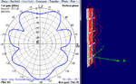
I am trying to design a dipole array parallel to a finite ground plane in 4NEC2.
but i did not find any option to set the dimension of ground plane in NEC, Instead I made grid of wires to substitute for ground plane but it is not working in a correct way.
Please can some guide me how to set the dimension of ground plane.
I have attached snapshot of the plot in NEC.
Untitled.png
 

Making a ground plane using mesh is standard in NEC based simulators. Your mesh looks fine enough given the distance between the dipole elements and ground plane.

I would increase the width of the ground plane in horizontal (Y) direction so the total width is close to a full wave. With the current ground plane size, you lose gain.

How do you know it is not working as expected?

Did you check the current distribution in the ground plane and antenna elements (to detect non connecting segments or a diverging simulator)?

Did check the phase between the 4 dipole elements?
 
The distance between the ground plane and array is lambda/10;
between the array element it is lambda/2. I should get one main lobe with two side lobe.
you can see the current distribution on the element and pattern.
I excited all of the elements with one volt and zero phase.

- - - Updated - - -

**broken link removed**
I should get pattern like this one attached.
 

Attachments

  • Untitled1.png
    Untitled1.png
    57 KB · Views: 139

Your graph indicates maximum gain of 24.7 dBi. You will never reach that with a 4 element half wave dipole array. Expect 15 dBi, but with a wider ground plane. Are you sure you have no perfect ground below the antenna (to avoid the about 6 dB gain because of ground reflection).

Do you have also heat graph (I mean a graph that converts current to wire color)?

If that graph is from your simulation, you likely violated the modelling rules for NEC.
 
Untitled4.png
I want to add perfect ground plane below array but with finite dimension so that gain can increase.
Also, i tried the same problem with array above infinite pec and i got the required plot which is attached.
why i can not simulate ground plane with finite dimension. ?
Your graph indicates maximum gain of 24.7 dBi. You will never reach that with a 4 element half wave dipole array. Expect 15 dBi, but with a wider ground plane. Are you sure you have no perfect ground below the antenna (to avoid the about 6 dB gain because of ground reflection).

Do you have also heat graph (I mean a graph that converts current to wire color)?

If that graph is from your simulation, you likely violated the modelling rules for NEC.
 
Last edited:

You can simulate a finite ground, but you will get more side lobes and some backwards radiation. As I mentioned before, you need to increase the width of the ground plane, it is too narrow. It will give you more gain.

Make sure that you don't have infinite PEC ground (in XY plane) when simulating your antenn with vertical finite ground.
 
Status
Not open for further replies.

Part and Inventory Search

Welcome to EDABoard.com

Sponsor

Back
Top