Vermes
Advanced Member level 4

This is a project of a multifunctional charger. The maximum performance is achieved with maintaining simplicity and reliability.
Features of the device:
- charges Pb (acid) and Li-Ion accumulators
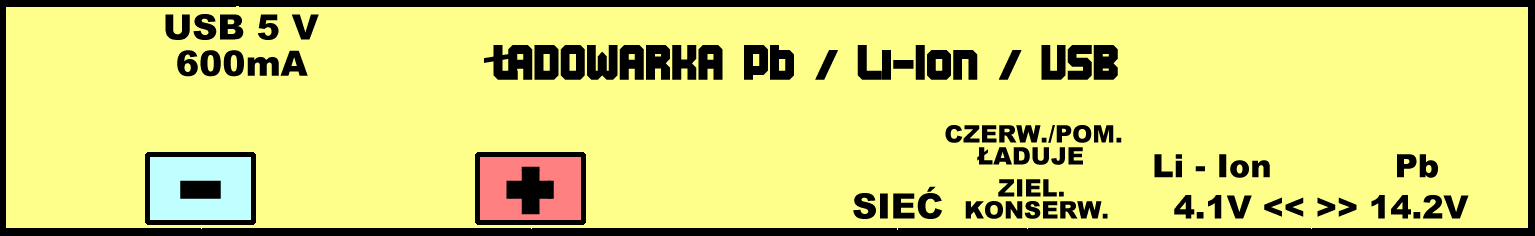
- has USB output with voltage 5V 600mA to charge USB devices
- charging indicator (charging, charged, no accumulator)
- insensitive to the polarity mistakes and short circuits
- does not discharge accumulators with power failure
- Li-Ion charging current about 400mA, Pb 1...1,4A
System:
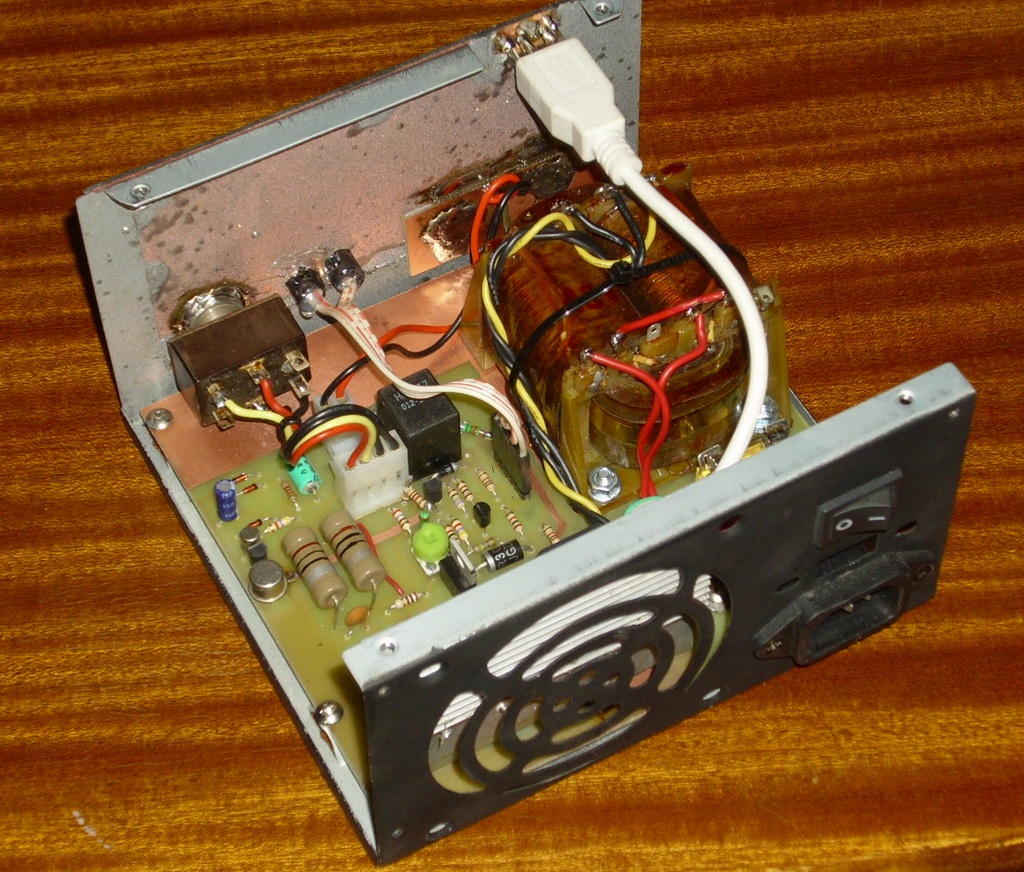
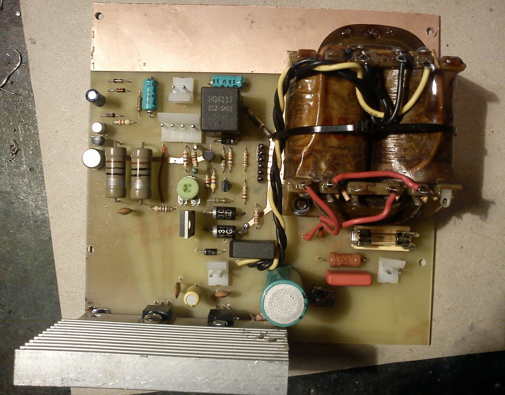
The system is powered by a mains transformer wave rectifier. The system uses a rectified pulsating voltage of the network for the intended function, so if someone tried to add a filtering capacitor after the bridge, it would be impossible because both the automatics charging system and current indication would not work. Transformer should give about 18V of AC voltage, have 25...30W power and split secondary winding (in order to supply a lower voltage of USB stabilizer 5V). LED3 indicated connecting to the network. The board was made with a marker.
Charging system:
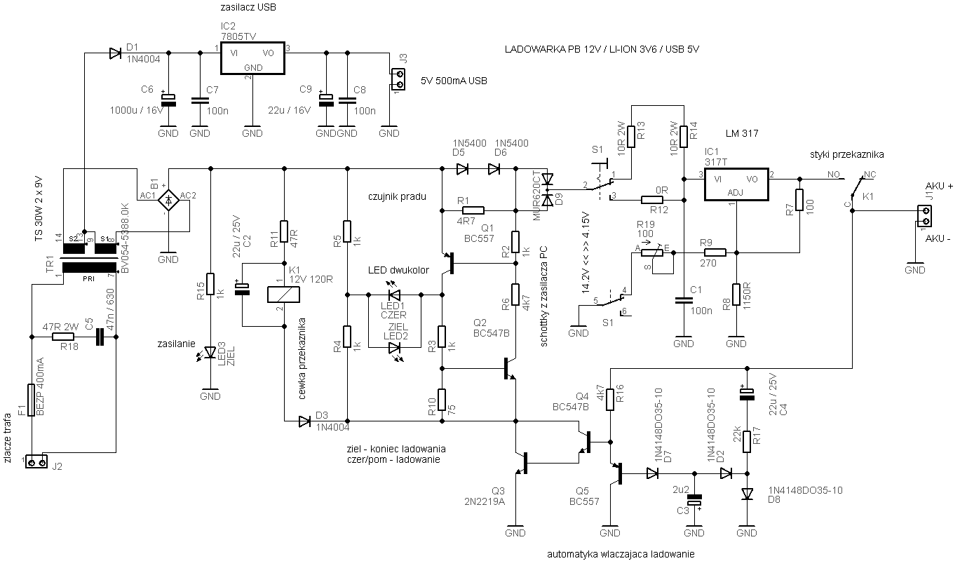
Charging by constant voltage with current limiting. For 12V accumulator charging, the current limiting is provided by stabilizer LM 317, performance of the transformer and optional resistor R12. For 3,6V accumulator charging, current is limited by resistors R13 and R14. Voltage is set by divider R7, R9, R8 and R19. Suitable resistors are connected by a selector switch of accumulator type S1. R8 should be selected for a 12V accumulator until you gain 14,1...14,2V. After selecting this resistor you can switch S1 to position 4,1V (Li-Ion) and precisely set charging voltage using R19. In this type of accumulator it is very important. 4,1V is a safe value for all types, although you can also use 4,2V. You should connect temporarily electrolyte 1000uF/25V to the bridge B1 at the time of voltage adjustment and connect for a moment any accumulator, or short the collector and emitter Q3. The system should snap in mode. This will facilitate voltage measurements that can be done at this time without accumulator.
Diode D9 (Schottky) provides turning off the relay in case of supply voltage failure. Any other diode of this current can be used, in this project it was Schottky because of its lower voltage drop. Without the D9 diode, current from accumulator would flow to R11 via stabilizer LM317. It has a built-in protective diode connected in the direction from output to input.
Enable charging:
Plug in an accumulator results in opening the transistors Q3 and Q4 in Darlington system. Q3 is BC211 because of a large current of the relay coil. Conductive transistors turn on the relay coil by diode D3, which prevents the appearance of negative pins on the collector Q3 and emitter Q2. Resistor R11 reduces the voltage across the relay coil and the capacitor C2 filters it (and is responsible for the previously mentioned pins). Relay contacts attach the positive terminal of the accumulator to the IC1 stabilizer.
Disable charging:
In the absence of the accumulator, rectified pulsating voltage appears at the output. This voltage, after separating the DC component by C4 capacitor, is rectified by the diode D2, charging the capacitor C3 with negative current. This causes current flow through D7, which after amplification by transistor Q5 causes clogging of Darlington system with transistors Q3 and Q4 and thus disconnects the relay. Diode D8 ensures the symmetry of the rectifier impedance to prevent the capacitor C4 from „clogging by voltage”. It is necessary, due to the fact that the converter is sinusoidal. Resistor R17 reduces the current flowing through the diodes and protects capacitor C4 against damage in case of reverse connection of an accumulator. For 12V accumulator connected „plus to minus” current flowing from it is less than 2mA. The same is its value when the accumulator is properly connected, but with no power supply of 230V.
Current sensor:
Measure element is resistor R1. Diodes D5 and D6 protect against excessive voltage drop on it, while the charger gives a large current. At sufficiently high current, voltage accmulated across the resistor R1 causes the activation of the base of transistor Q1 via resistor R2. This in turn changes the direction of current flow through the two-colour diode in the bridge made of elements: R4, R5, R3+R10 and joint C-E of the transistor Q1. Reverse the current flow causes the diode lights up in red instead of green structure. Transistor Q2 provides a positive feedback to remove the deadlock in the system, when no colour in the diode is lit or lit poorly. At the moment of increased voltage on R10 due to opening Q1, transistor Q2 through resistor R6 distorts base Q1, causing its saturation. With each half-period of voltage, the system is back not snapped, which prevents against continuous lighting red diode, even at low charging current. Thanks to the transistor Q3 which controls the relay, when there is no accumulator, the whole system that indicated the charging is off (diode off).
- small current (maintenance, charging): diode lights green
- large current (12V accumulator charging): diode lights orange
- large current (3,6V accuulator charging): diode lights red
Different colours of diodes light during charging (orange and red) result from different switch moment of the red during half-periods of the network. For 3,6V accumulator, current reaches the threshold earlier and almost the entire half-period the red diode lights.
Threshold of lighting up the red diode depends on the resistor R1 and voltage B-E of the transistor Q1. In the model it was about 50mA which seems to be the optimal value for the expected accumulators.
USB power supply:
Standard application of stabilizer 7805. Voltage is rectified by a negative half of the bridge B1. Diode D1 seems to be unnecessary (the system of power supply 5V works without it), but the absence of that diode causes incorrect work of the main charger, because voltage passes from C6 to bridge B1. Voltage for power supply 5V was taken from the center tap of the transformer.
Scheme:
Inscription for the front:
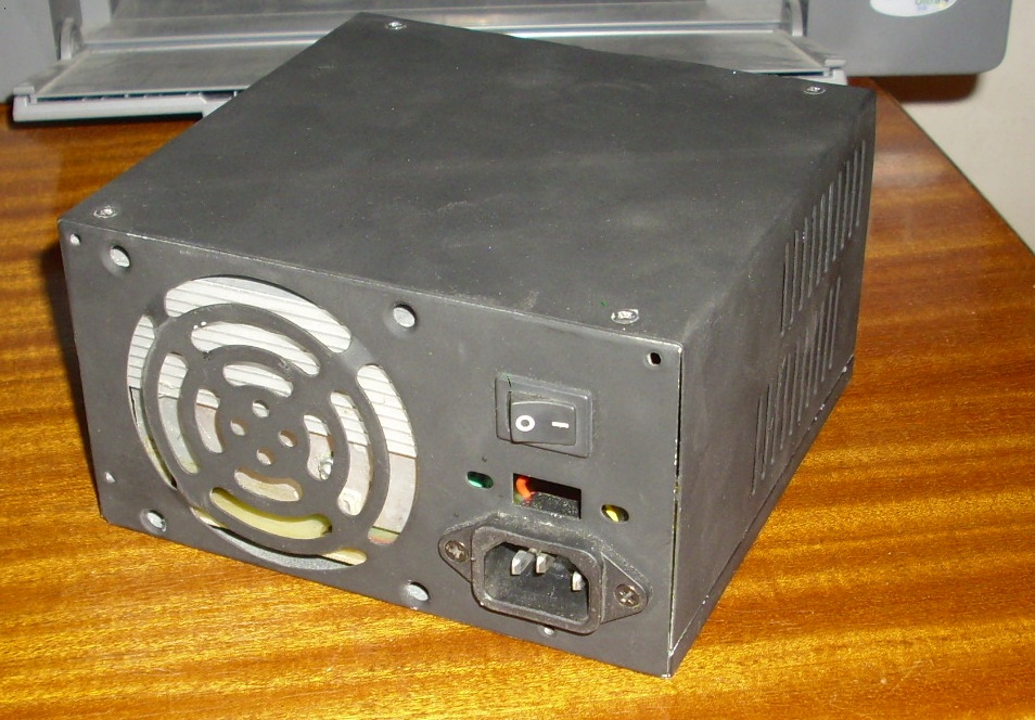
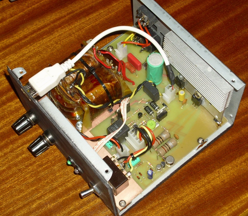
Pictures:


Link to original thread (useful attachment) – Ładowarka Pb, Li-Ion, USB