jeff0283
Junior Member level 2
Hi I am doing a PA's linearization using a series Schottky diode connected at PA's gate terminal.
I choose the Avago HSMS280F,and here is the datasheet:
I am trying to tune the diode to achieve gain expansion and decreasing phase shifting, to compensate AM-AM and AM-PM distortion of my PA.
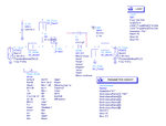
My schematic is as the attachment.
After sweep the series R(1k~16k Ohm) and the parallel C(1pF~20pF),
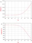
I find when R=15k, C=2pF ,the result can achieve gain expansion and decreasing phase shifting, but the difference is too small.
(For gain expansion,dB(S21)=-0.13dB@Pin=-20 dBm, dB(S21)=-0.11dB@Pin=20dBm delta=0.02 dB)
(For gain expansion,phase(S21)=4.11 degree@Pin=-20 dBm, phase(S21)=3.97 degree@Pin=20dBm delta=-1.4 degree)
How can I adjust my schematic to have a bigger defference?
I have attach my ADS workspace.
Thanks~~
I choose the Avago HSMS280F,and here is the datasheet:
I am trying to tune the diode to achieve gain expansion and decreasing phase shifting, to compensate AM-AM and AM-PM distortion of my PA.
My schematic is as the attachment.

After sweep the series R(1k~16k Ohm) and the parallel C(1pF~20pF),
I find when R=15k, C=2pF ,the result can achieve gain expansion and decreasing phase shifting, but the difference is too small.

(For gain expansion,dB(S21)=-0.13dB@Pin=-20 dBm, dB(S21)=-0.11dB@Pin=20dBm delta=0.02 dB)
(For gain expansion,phase(S21)=4.11 degree@Pin=-20 dBm, phase(S21)=3.97 degree@Pin=20dBm delta=-1.4 degree)
How can I adjust my schematic to have a bigger defference?
I have attach my ADS workspace.
Thanks~~
Attachments
Last edited by a moderator: