PG1995
Full Member level 5
Hi
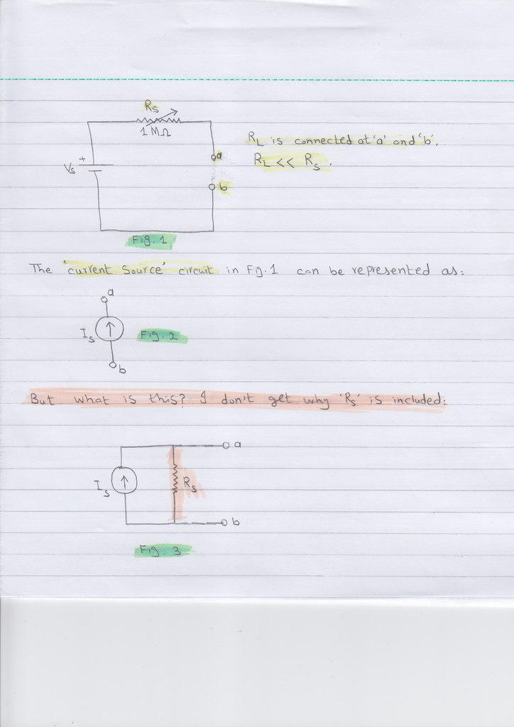
I have always thought of a current source as a very, very high voltage supply with a very, very large resistor, Rs, in series (I mean this large resistor would make series connection with the load resistor, RL). The larger the series resistor, Rs, the less effect the change in load resistor has on the load current. The Rs should be a variable resistor which is adjusted to get the wanted current through the RL. In other words, a current source is also a special type of voltage source.
In a regular voltage source the Rs is very small which can be adjusted to vary the voltage across the RL. If you want more volts to appear across the RL then you need to decrease the resistance of Rs.
Please correct the stuff above if you deem something wrong. Thanks
Now I'm coming to the main question(s).
Please have a look on the linked diagram (or attached one):
https://img843.imageshack.us/img843/3518/imgan.jpg
A current source is represented as shown in Fig. 3 in the linked and attached diagram with the Rs in parallel configuration. I don't get it. Why? As I say above, in my view, a current source is a special kind of voltage source. They say, Rs, is an internal resistance and makes a parallel connection (as shown in Fig. 3). I don't get it. Do you get where I'm having problem? Please help me. Thanks
Regards
PG