Hawaslsh
Full Member level 3
- Joined
- Mar 13, 2015
- Messages
- 164
- Helped
- 5
- Reputation
- 10
- Reaction score
- 7
- Trophy points
- 1,298
- Location
- Washington DC, USA
- Activity points
- 3,422
Hello All,

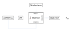
I have a frequency synthesizing PLL that was designed in Analog devices' ADIsimPLL software. A picture of the block diagram is above. The PLL is within the dashed block. It consists of a VCO, HMC582 , and the phase detector/charge pump, ADF4153A. The PLL alone works as expected. However, when I attach a power amplifier, HMC7357, to the output of the VCO the PLL is only conditionally stable. The amplifier is a GaAs FET; at Pinch-OFF (~-1.4V) the PLL works as expected. Once I tune the gate bias < -0.93V the PLL becomes unstable.
One clue I have, the lock voltage is ~4V to achieve the frequency I need. The max voltage for the charge pump is 5V. It can't not be coincidence that once i tune the gate voltage down 1V i start to see issues. I can go into much more detail if needed, but does anyone have an explanation as to why this is happening? The block diagram of the VCO shows a buffer amp on the output I am using, so I am currently stumped.
I can provide more detail if needed,
Thanks in advance,
Sami