Continue to Site

Welcome to EDAboard.com

Welcome to our site! EDAboard.com is an international Electronics Discussion Forum focused on EDA software, circuits, schematics, books, theory, papers, asic, pld, 8051, DSP, Network, RF, Analog Design, PCB, Service Manuals... and a whole lot more! To participate you need to register. Registration is free. Click here to register now.

Output showing 1 when no input voltage is applied in Data of D flip flop

Status
Not open for further replies.

Shahed47

Newbie level 4
Joined
Mar 30, 2016
Messages
5
Helped
0
Reputation
0
Reaction score
0
Trophy points
1
Activity points
52
Hi,

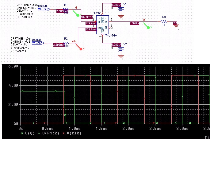
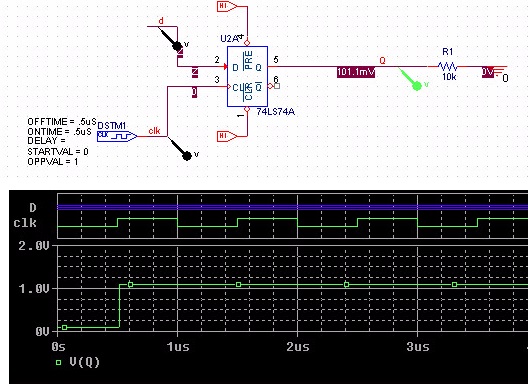
I am working on D flip-flip. Therefore, I tried to do simulation, it giving me output voltage when I am keeping the Input D floating or no voltage is applied to it. Could someone explain me what is the reason for it. Thanks in advance.

2705192400_1474494470.jpg
 

TTL and LSTTL series floating inputs are always read as '1'. Don't know what you mean with "no voltage applied"? To assure no input voltage, connect the signal to ground.
 
Hi,

While unconnected TTL inputs show a logic 1, this is different to CMOS inputs.

Don't leave CMOS floating.
This may cause different problems.

Therefore I say that all inputs need a true logic input state. Either internally or externally forced.

Klaus
 
Both of the above comments are very true for physical ICs. However I note the OP mentions that this is on a simulator.
Depending on how the simulator was written and whether it simulates at the TTL/CMOS/whatever component level or just the simulates the functionality, it can basically do whatever the code writer wants in undefined situations (such as floating inputs).
Susan
 
Thanks a lot. The explanations helped me for Orcad Pspice simulation as well as for Physical IC's implementations. Now, I have another question: in Pspice orcad simulation why output voltage for D flip flip showing 3.73 volts, where I am expecting 5 volts. I am giving input 5 volts (digital 1). Is that simulator was written in that way for digital 1, analog output be around 3.75 volts?

Thanks a lot again.

I have attached the simulation and output for convenience. (Orcad Pspice CIS)

9372851600_1474570469.jpg
 

Hi,

A CMOS device will switch very close to 5V, but not a LS.
2.0V is considered to be a logic HIGH, so 3.7V is well within specification.
And the simulation meets true real conditions.

It seems you need to read about logic families, logic voltages, and behaviour..

Klaus
 
Does anybody use an old fashioned 74LS74A anymore? I stopped using them about 35 years ago.
It datasheet shows that its output is an emitter-follower in series with a diode so of course its output high cannot go as high as 5V.
Why not look at the datasheet?? The datasheet shows that its minimum logic high output voltage is only 2.4V and the typical logic high output voltage is 3.4V.
 
Hi,

True..
* power consuming
* slow
* weak output levels
* high input current

I don't see a benefit either. Are they cheaper? (But one have to take into account that one needs a bigger power supply, increased heat will reduce reliability. Maybe planned obsolescence?)

Klaus
 
Logic families have evolved over the years. The first family was RTL that I never used then DTL, ECL that I also never used, TTL, LS-TTL, then Cmos.
 
Currently I am doing a circuit Orcad capture CIS simulation for D flip flip. I am giving pulse to the D and Clk at the same time, but I am playing with delay by changing the value of the RC. When clock is delayed, it is showing output 3.4 (digital 1) as expected. But when data is delayed it showing value 1.1 V. But, I am expecting 0 V or close to it (50 mV) or Digital 0 when data signal is delayed.

Figures are attached for convenience. First figure is for delayed clock which giving me digital 1, but in the second figure I am getting undefined value (1.1 V) instead of 0.

I want to know if there any explanation. Also, if there any suggestion how to get digital 0 (analog voltage around 100 mV or less as datasheet defines) in simulation.

https://obrazki.elektroda.pl/1749761600_1475007783.jpg

https://obrazki.elektroda.pl/9306474600_1475007808.jpg
 

I'm not sure where you see the 100 mV Vol specification in 74LS74A datasheet (which manufacturer?), but the D and CLK input voltage is above Vil specification. In so far the result is unpredictable.
 
From the first figure we can see that the output is staying unpredictable stage for few micro seconds, then it changed to digital 1. I was expecting for that kind of output for digital 0 as well. But, for the second circuit setup, it stays unpredictable stage for whole simulation.

Is there any explanation for that?

I am using TI data sheet:

https://www.ti.com/lit/ds/symlink/sn74s74.pdf
 

Hi,

Maybe you are driving the gate into metastability.

This usually is when you violate setup time or hold time.
From your timing it seems you are within the specification of -20/+5ns.

But there is an additional problem with your simulation.
You are using RC, this causes the inputs to stay relatively long between true_low and true_high.

If you have stable (and valid) levels at the output with stable data_input, then this is an indicator that your simulation shows the metastability problem.

Klaus
 
  • Like
Reactions: Shahed47

    V

    Points: 2
    Helpful Answer Positive Rating

    Shahed47

    Points: 2
    Helpful Answer Positive Rating
A metastable state would end latest after a few ns for slow logic like LS TTL. Seeing a stable intermediate output voltage is hardly metastable behavior.

First point is that we are discussing simulation results, not real hardware. The simulation model must not necessarily represent the component behavior completely.

Secondly, you are applying "illegal" input voltages slightly above Vol. This may be well sufficient to get the unexpected output voltage. Instead of guessing about you simulation results, why don't you correct the input voltage first?
 
  • Like
Reactions: Shahed47

    V

    Points: 2
    Helpful Answer Positive Rating

    Shahed47

    Points: 2
    Helpful Answer Positive Rating
Status
Not open for further replies.

Part and Inventory Search

Welcome to EDABoard.com

Sponsor

Back
Top