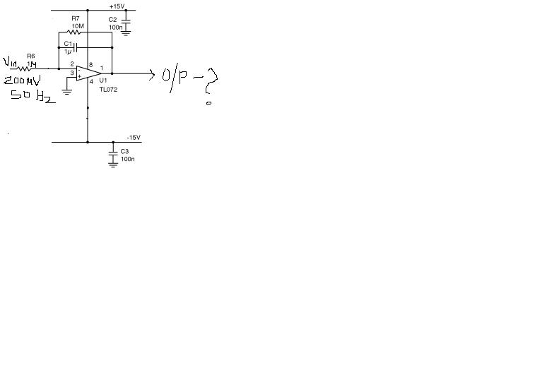
Welcome to our site! EDAboard.com is an international Electronics Discussion Forum focused on EDA software, circuits, schematics, books, theory, papers, asic, pld, 8051, DSP, Network, RF, Analog Design, PCB, Service Manuals... and a whole lot more! To participate you need to register. Registration is free. Click here to register now.
Added after 5 minutes: This will not help too much, because of the large time constant. Remove the capacitor, because you have a low pass with a corner frequency below 1 Hz !!
If the schematic is correct, there must be a DC offset at the said 200 mV input, otherwise the output would be 0V DC and about 0.6 mV AC. The resistors have rather high level, but the TL072 input current is in the pA range and can handle it.
As you apparently expected a different result, you should recalculate the amplifier dimensioning.
This site uses cookies to help personalise content, tailor your experience and to keep you logged in if you register.
By continuing to use this site, you are consenting to our use of cookies.