Continue to Site

Welcome to EDAboard.com

Welcome to our site! EDAboard.com is an international Electronics Discussion Forum focused on EDA software, circuits, schematics, books, theory, papers, asic, pld, 8051, DSP, Network, RF, Analog Design, PCB, Service Manuals... and a whole lot more! To participate you need to register. Registration is free. Click here to register now.

Oscillator gain

Status
Not open for further replies.

Atif Hussain Shah

Member level 1
Joined
Jun 11, 2020
Messages
41
Helped
0
Reputation
0
Reaction score
0
Trophy points
6
Activity points
438
I am design an oscillator circuit for broad band range i-e from 100MHz to 200MHz.

The resonance frequency of the resonator changes from 100MHz to 200MHz as the Er of the substrate changes. The loss of resonator is around 4dB and its phase is around 150 to 170MHz.

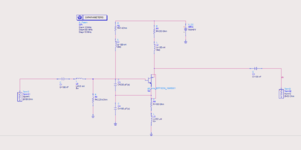
With that resonator, I want to connect an amplifier in reflective mode so that the oscillator circuit completes.

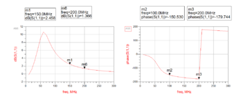
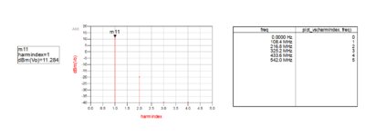
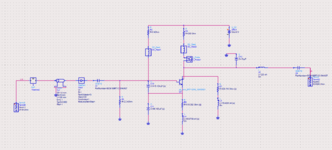
The phase of amplifier is equal and opposite to the phase of Resonator so the phase condition of Bark-Hausten criteria is met but the gain of amplifier is less than the loss of resonator in 150 to 200MHz range. So Second condition of oscillator is not met in range 150 to 200MHz. The ciruit and response of Amplifier is attached below. How can I increase the gain to 4 dB. In full range(100 to 200MHz) of Amplifier.

@big Boss please help
 

Attachments

  • Amplifier.PNG
    Amplifier.PNG
    28.3 KB · Views: 123
  • Amplifier responce.PNG
    Amplifier responce.PNG
    42.5 KB · Views: 120

Bigboss another problem i saw is that in transient simulation, the amplitude drops down. Is this related to transient simulator setup?

1654809406237.png


the settings of transient simulator are
1654809517589.png
 

You have already a Load at Collector ?? It's impossible to get Oscillation signal from Coaxial Resonator side in this configuration. I think you're doing something wrong.
BigBoss i think 50ohm termination is fine at the output. I had designed a circuit at 100MHz 2 years ago, and it worked perfectly. in that case i was taking output from emitter. You can see termination at 50ohm.


1654847299060.png


1654847437927.png


As 20dB attenuator has been used so output power is around +11dBm.
Its ADS results are attached
1654847538697.png
 

I write down 3 references for oscillator design. read those texbooks and work on math. and practical examples. Otherwise you go blind and you confuse all. OK ? You have to know what you're doing.

"Discrete Oscillator Design: Linear, Nonlinear, Transient, and Noise Domains", Randall W. Rhea
"RF and Microwave Transistor Oscillator Design", Andrei Grebennikov. 2007 Wiles and Sons
"Design of Modern Microwave Oscillators for Wireless Applications: Theory and Optimization", Ulrich Rohde. 2005 Wiley Interscience
 
Big Boss I am reading the books and I am very thankful to you for providing them.
I have made some improvements by reading them.

The harmonics has been reduced and now the second harmonic is 30dBc below than the fundamental signal. Before it was only 5dBc below the fundamental.

Also I have done the Negative resistance analysis and observe the oscillating frequency where imaginary part crosses the zero line.

And oscillating frequency has also been observed using one port analysis by looking the magnitude and phase of S11.


I have attached the results.
But I have not been able to run Transient simulation. Can I share the workspace so that you may have a look.
 

Attachments

  • Oscillating Point Using S11.png
    Oscillating Point Using S11.png
    30.3 KB · Views: 83
  • Negative Resistance.png
    Negative Resistance.png
    27.4 KB · Views: 75
  • HB Simulation.png
    HB Simulation.png
    24 KB · Views: 77
  • Oscillator Schematic.png
    Oscillator Schematic.png
    61.8 KB · Views: 78

Status
Not open for further replies.

Part and Inventory Search

Welcome to EDABoard.com

Sponsor

Back
Top