Welcome to our site! EDAboard.com is an international Electronics Discussion Forum focused on EDA software, circuits, schematics, books, theory, papers, asic, pld, 8051, DSP, Network, RF, Analog Design, PCB, Service Manuals... and a whole lot more! To participate you need to register. Registration is free. Click here to register now.
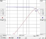
Doing a linear simulation using the provided S-parameters from MACOM, can see from the attached picture, that the S-parameters use the matching components tuned on 1.8GHz.
The component values are given at the beginning of the text file:
Most probably the modules that you are using are also tuned on 1.8GHz, and each of them having 28dB of gain is no wonder that you get an oscillation on that frequency, when you cascade them.
You have to find the S-parameters of the chip itself, without any matching network, and after that, do your own impedance matching and stability optimization for the desired frequency.
To see how to apply correctly K-factor in a multistage amplifier read this:
This shows that DC lines are carrying RF signals, and that oscillation depends on that effect.
I asked twice for a photo of the setup, but you just show a sketch of the RF patch, ignoring all the real setup with DC lines. Makes no sense to me, if the trouble is related to RF on the supply lines. But anyway, it's your project, so good luck!
I have tried by putting both in a metal box , but the problem remains the same. I have found that the input return loss is poor at our frquency of interest in both evaluation boards. so, I think , there is a problem. please verify and guide.
I am terminated the input port. and when I turn of DC for both MACOM LNA , the oscillations occurs( RF out port is connected to spectrum and RF input port is terminated).
Using dev boards from the manufacturer reduces a lot potential issues, but it's still possible that the wiring for DC power is part of the problem. Putting some ferrite beads of the proper material might help a lot.
Simply putting the circuit inside a metal box likely won't help. It will just act to funnel more energy from the output towards the input. Lining the metal box with absorbing materials could help. Or putting each LNA stage in a separate box.
The easier thing to do is probably to put a small attenuator (try 3dB) between the two stages. Or use a more stable, internally matched amplifier as the second stage. I doubt having LNAs for both stages significantly helps your NF.
This site uses cookies to help personalise content, tailor your experience and to keep you logged in if you register.
By continuing to use this site, you are consenting to our use of cookies.